This product is intended to reduce electromagnetic interference (EMI).
Its use should be considered only if interference remains after best
wiring and grounding practices have been implemented at the location.
Because of the variety of equipment locations, power wiring methods,
and grounding practices, it is impossible to ensure a specic amount
of interference suppression. Although Franklin Electric has performed
laboratory tests that show signicant EMI reduction with this lter, we
cannot predict the performance of this product in the eld.
Refer to the SubDrive Utility Installation Manual for detailed setup
and safety information, refer to www.franklinwater.com.
Installation
Remove System Power
Risk
of severe injury or death by electrical
shock.
• Disconnect and lock out all power before installing or servicing
equipment.
• Capacitors inside the drive and the lter can still hold a lethal
voltage even after power has been removed — ALLOW FIVE
MINUTES FOR DANGEROUS INTERNAL VOLTAGES TO
DISCHARGE.
Risk of bodily injury or damage to pump or other
equipment.
• This product should only be used with the Franklin Electric
SubDrive Utility (UT2W) drive models 5870202003 and
5870202003XD.
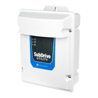
Mounting
The SubDrive Utility System Filter is supplied in a NEMA 3R enclosure. Appropriate cables and cable ttings must be used in
the installation to maintain the NEMA 3R rating.
1. Remove the thumbscrew from the bottom front cover of the System Filter.
2. Remove the cover from the System Filter.
3. Mount the System Filter to a at surface using three screws (not included). Insert one screw through the top ange hole,
and then two screws into two internal mounting holes.
Electrical Connections
Remove System Power
1. Disconnect electrical power to the controller at the main breaker. If previously connected to the supply mains, wait ve (5)
minutes for dangerous internal voltages within the controller to discharge.
2. Remove the cover from the SubDrive Utility controller following instructions in the SubDrive Utility manual.
Install Wiring
(
Tighten all terminals to 5 in-lbs (0.55 Nm))
3. Route supply mains power and ground wires to the System Filter terminals L1 and L2 (230 V) or L and N (115
V) with the green ground wire connected to the marked ground terminal.
4. Route power and ground wires from the System Filter terminals L1 and L2 (230 V) or L and N (115 V)
to the SubDrive Utility controller drive input terminals L1 and L2 (230 V) or L and N (115 V) respectively, with the green
ground wire connected to the marked ground terminals.
TH1
MH1
230V L1 L2
115V L N
J1
P1
TH1
MH4
BLK BLK
RV9
J4
C55
P4
P3
C103
R133
R148
C102
C66
R251
MH1
J11
TVS1
R64
R2
D3
R1
R3
U2
C5
R17R18
D5
D1
D2
L1
T2
RV2
J6 J1 J13
RV1
SENSOR TRANSDUCER FAN
PRESSURE
226115103 REV 2
CONTROL PCB
USB
PS
FAN
XDCR
P
S24
1 1 1
R100
R101
R102
R103
R104
R105
R106
R107
1 8
81 65432 7
ON ON
R87
R88
R89
R90
R91
R92
R93
R94
1 8
81 65432 7
R30
R34
R35
R39
R40
R41
R42
R43
1 8
81 65432 7
UNDERLOAD
P2
P4
SW3SW2SW1
R74
R82
R81
R80
R79
R73
R72
R71
R78
R86
R85
R83
R84
R108
R24
R21
R31
C23
C18
R110
R77
R75
R76
R33
R25
C26
R32
R26
R19
C13
C16
C17
C11
R13
C19
C20
R70
R15
C25
R38
C24
R23
R16
R20
R12
R14
U5
D7
D4
J5
TP4
TP2
TP1
TP3
J3
U3
D6
R28
D13
D12
R29
R69
C15
C14
EGND
INTERBOARD
RS485
R22
C21
C22
C10
R36
R27
U4
Y2
C22
R109
J9
TO MOTOR FROM DRIVE OUTPUTPOWER INTO DRIVE INPUT
RED
BLK
YEL
BLK
BLK
X
BLK
X
3 WIRE
2 WIRE
RED
BLK
YEL
BLK
J1 J2J3J4
T5 T2 T1 T6 T4 T3
BROWN
BLUE
BLACK
YELLOW
WHITE
RED
225387101 REV0
RoHS
Compliant
BLK
BLK
BLK
BLK
GND
GND
L2/N
L2/N
L1/L
L1/L
GND
L1 L2
L N
230V
115V
L1 L2
L N
GND
L1/L
L2/N
GND
GND
BLK
BLK
From AC power,
per SubDrive rating
To pump/motor
5-3/4"
146.05 mm
8-1/2"
215.90 mm
2-5/8"
66.68 mm
Weight
6 lbs
2.72 kg
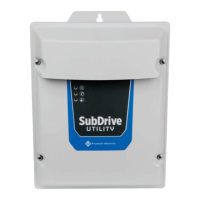
SubDrive Utility 2 Wire - System Filter
INSTALLATION GUIDE