ASSEMBLING THE ENGINE ASSEMBLING THE ENGINE
18 19
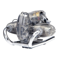
Step 10. Oil cooler
The oil cooler must be fitted at
this time. This is in two parts
(32 & 33), and should be
assembled so that the parts
clamp to the T-shaped
moulding on the side of the
crankcase. Hold the smaller
inner part (33) in place, then fit
the larger outer part of the
cooler (32) to this and secure
with two screws.
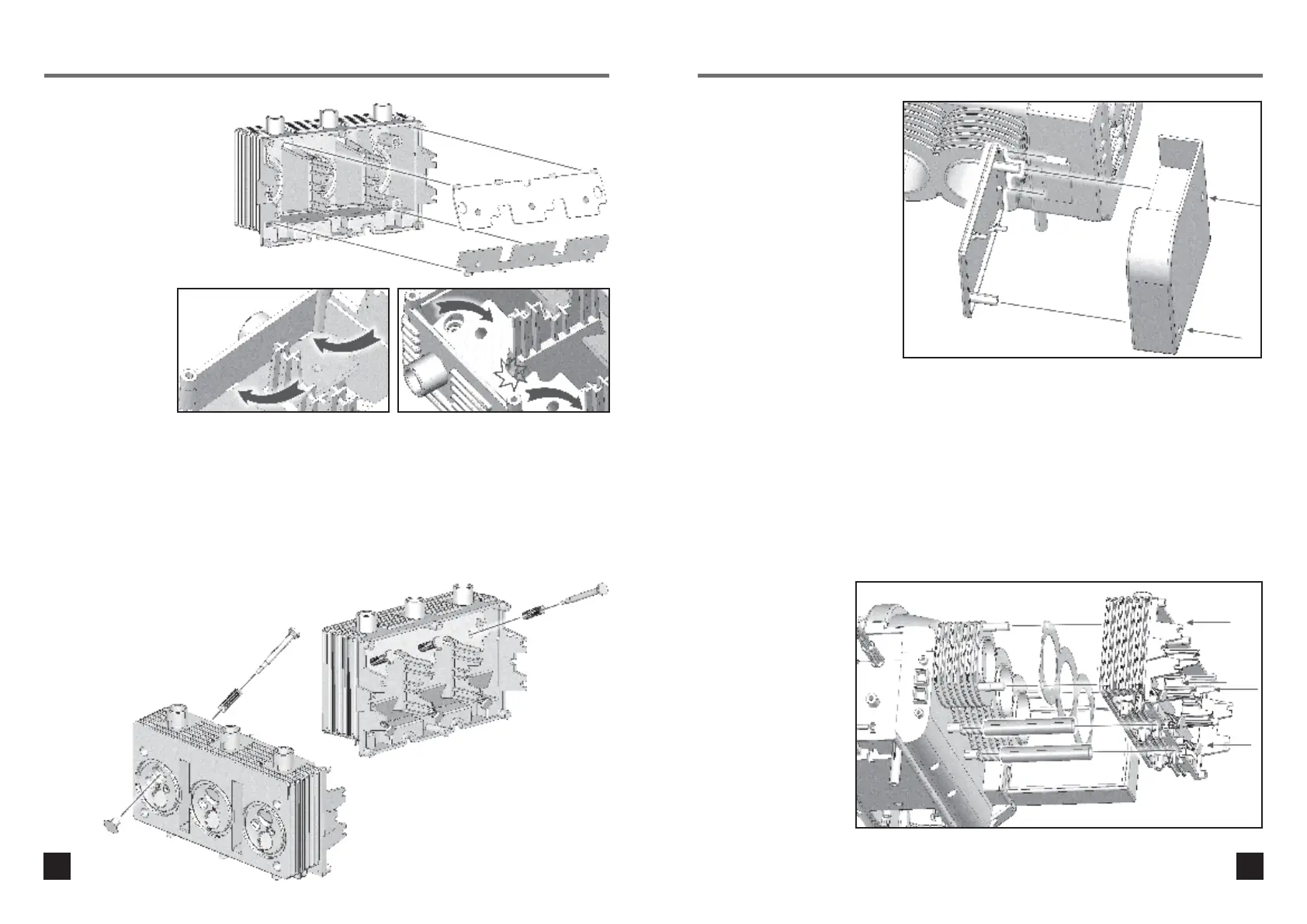
Step 11. Cylinder head –
right side
Place a paper cylinder head gasket over the
right hand cylinder barrels. Fit two oil return
pipes (27) to the moulded lugs on the side of
the crankcase, then fit the right cylinder head
(51) and secure with four screws.
Repeat for the other (left)
side of the engine, using
the other gasket, two oil
return pipes, and the left
cylinder head (50).
Step 8. Valve guides
Fit two valve guide plates to
each of the lower cylinder
heads. Note that each head
uses one narrow plate (55)
and one wide plate (54).
Each plate has three round
studs that face downwards
into the head. First fit the
tabs on the outside of
each plate into the
corresponding holes
in the side of the
head, then push the
plates down firmly
so they clip into
position (circled).
Step 9. Valve assembly
For each cylinder head, you will need six valves (9),
valve stems (7) and valve springs. Fit to the head as
shown. First slide a spring over a valve stem, and
insert into one of the six holes in the valve guide plates.
Gently compress the spring until the end of the stem
sticks out of the bottom of the head. Carefully push the
valve on to the stem. Note that the end of the valve has
a step – push the valve until it touches the edge of the
step. DO NOT force the valve – these parts are
delicate.