No. Description Qty
1 Connecting rod 6
2 Piston half 12
Cams (labelled A – F) 6
4 Bearing cap 6
5 Rocker arm 6
6 Timing tool 1
7 Valve stem 6
9 Valves 12
10 Crankshaft sprocket A 1
11 Crankshaft sprocket B 1
12 Camshaft sprocket 2
13 Gudgeon (piston) pin 6
15 Carburettor outer 2
16 Carburettor inner 2
19 Exhaust muffler upper 1
20 Exhaust muffler lower 1
21 Exhaust pipe left upper 1
22 Exhaust pipe left lower 1
23 Exhaust pipe right upper 1
24 Exhaust pipe right lower 1
25 Crankshaft pulley 1
26 Fan pulley 1
27 Oil return pipes 4
28 Exhaust manifold left upper 1
29 Exhaust manifold left lower 1
30 Exhaust manifold right upper 1
31 Exhaust manifold right lower 1
32 Oil cooler outer 1
33 Oil cooler inner 1
34 Fan housing 1
37 Idler pulley 2
41 Crankshaft 1
42 Cooling fan 1
No. Description Qty
47 Crankcase upper 1
48 Crankcase lower 1
49 Cylinder barrels 2
50 Cylinder head left 1
51 Cylinder head right 1
52 Upper cylinder head left 1
53 Upper cylinder head right 1
54 Large cylinder head plate 2
55 Small cylinder head plate 2
56 Crankcase rear 1
57 Cylinder head plate upper 2
58 Cylinder head plate lower 2
59 Cam belt tunnel left inner 1
60 Cam belt tunnel right inner 1
61 Cam belt tunnel left outer 1
62 Cam belt tunnel right outer 1
63 Cam belt tunnel middle 1
67 Drive gear 1
68 Crankshaft gear 1
69 Distributor gear 1
Cam timing belt 2
72 Spark plug lead mounting clip 1
74 Distributor bushing 1
75 Crankshaft gear B 1
76 Crankshaft gear C 1
77 Timing alignment pin 2
78 Fan housing rear cover 1
Valve spring 12
Cam shaft (140 mm) 2
Rocker shaft (118 mm) 4
Metal shaft (37 mm) 1
Head gasket 2
Base 1
Distributor/spark plug assembly 1
Label 1
References to the left or right side of the engine mean the left or right side when
viewed from the fan end. Cylinders 1-3 are on the left side of the engine and
cylinders 4-6 are on the right.
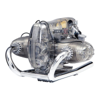
Identify the various parts by looking at the list of components and the
corresponding illustrations. Use a sharp knife to trim any excess plastic from the
components after they have been removed from their carrier frames.
Take care not to over-tighten the screws as this may permanently damage the
plastic.
- Non-rechargeable batteries are not to be recharged.
- Rechargeable batteries are only to be charged under adult supervision.
- Rechargeable batteries are to be removed from the toy before being charged.
- Do not mix old and new batteries.
- Do not mix alkaline, standard (carbon-zinc), or rechargeable (nickel-cadmium)
batteries.
- Batteries are to be inserted with the correct polarity.
- Exhausted batteries are to be removed from the toy.
- The supply terminals are not to be shorted-circuited.
NOTES AND ADVICE PARTS LIST
6 7