TGA300 Rev180405
27
WIRING
The following gures include the schematics, wiring diagrams, block diagrams,
and cables for the governor.
Connectors and Cables
The information available on the J1939 databus varies depending on the particular
engine type.
When a remote governor is installed ensure that the control module program code
P303 is set to REMOTE. Refer to Figure 5 for wiring details.
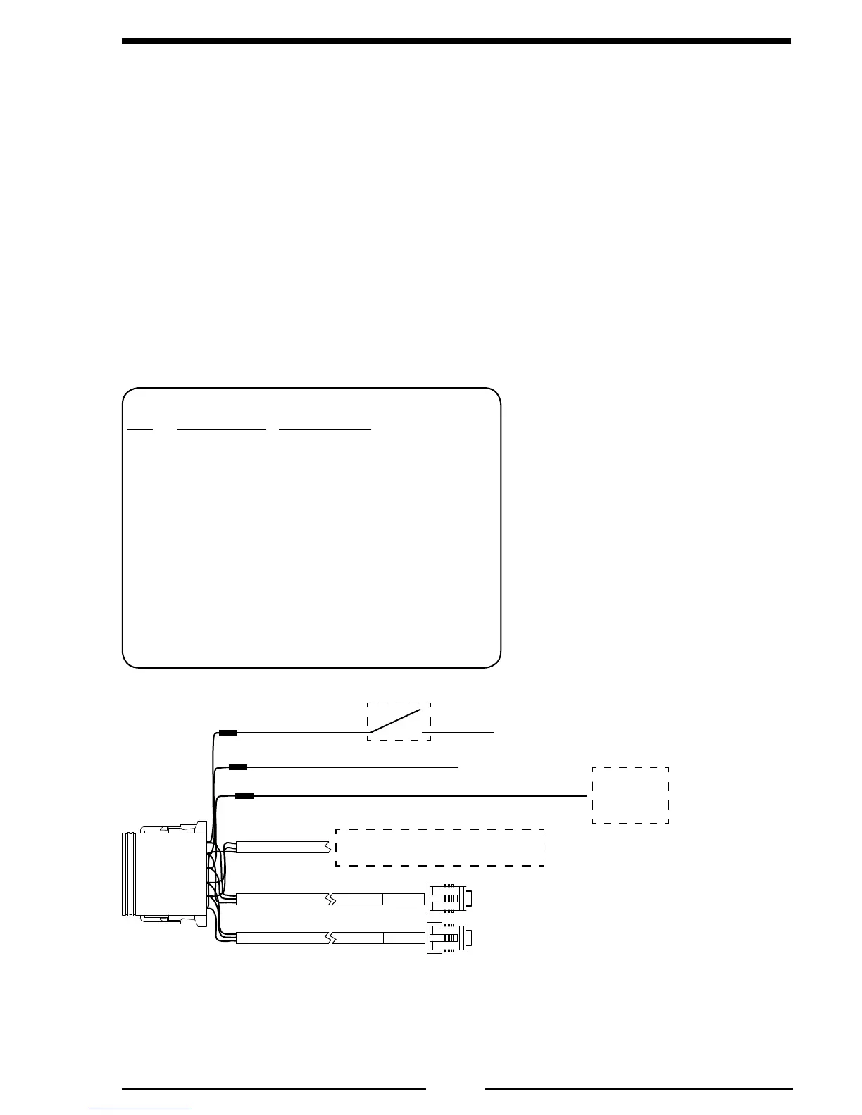
Figure 4. TGA 12-Pin Connector Wiring
12 Pin Connector/Cable
Pin Wire Color Description
1 Red +12 VDC Supply Power
2 Black Ground
3 White Interlock Input (+12 VDC)
4 Red J1939 CAN (+)
5 Black J1939 CAN (–)
6 Red +5 VDC Discharge Sensor
7 Black Ground Discharge Sensor
8 White Signal Discharge Sensor
9 Red +5 VDC Intake Sensor
10 Black Ground Intake Sensor
11 White Signal Intake Sensor
12 Yellow J1939 Shield
Note: The Interlock Input pin 3
must be made for the governor to
control the engine.
+12 VDC
Interlock
Circuit
To Discharge Pressure Sensor
To Intake Pressure Sensor
+12 VDC
GND
Ignition Key
RED
GRN
RED
BLK
WHT
To J1939
(See Engine Specic Wiring)
Standard sensor cable length is 10 feet.
12-Pin
Connector
 Loading...