TGA300 Rev180405
47
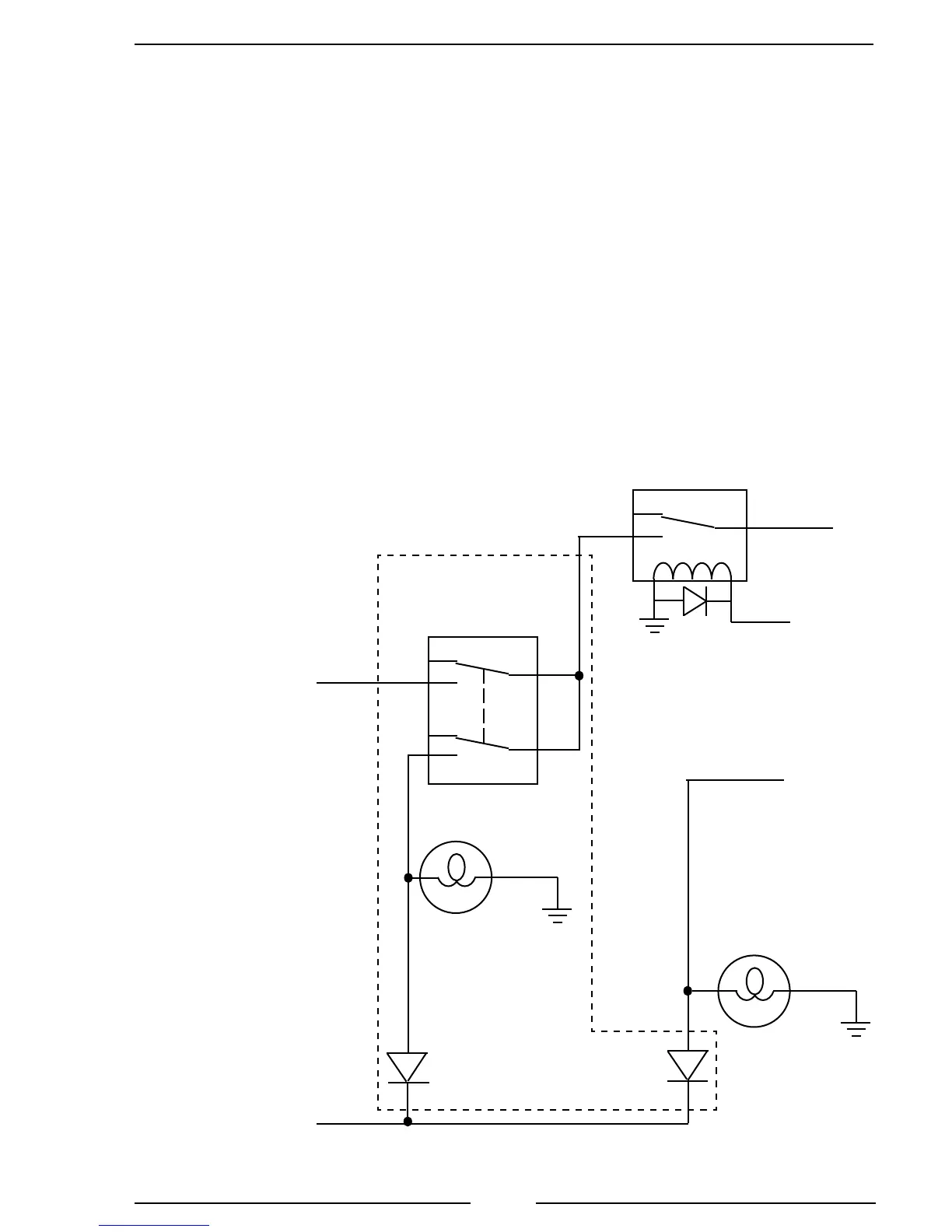
High-Idle Wiring
The governor includes a high-idle function. To activate the high-idle provide +12
VDC to pin 4 (High-Idle Active Input) of the 8-pin connector and to pin 3 (Interlock
Input) of the 12-pin connector. The high-idle connection to pin 3 must be isolated form
the interlock circuit using two diodes (see schematic).
Note: It is important that the connection to the Interlock Input from the High-
Idle circuit be isolated from the apparatus interlock wiring with the two
diodes. Refer to the wiring diagram. The pump must NOT be engaged
when using the high idle function.
The high-idle is set to 1000 RPM at the factory. (This value varies depending on
the specic engine.) To adjust this setting refer to High-Idle in the Operation Section.
Figure 22. High Idle Wiring
To 12-Pin Connector
Pin 3 White Wire
Interlock Input
To 8-Pin Connector
Pin 4 White Wire
High-Idle Active Input
A High-Idle Kit is available from FRC.
Includes:
ON/OFF Switch
Indicator Light
Two Diodes
From
Transmission
Neutral
+ VDC
Pump
Engaged
Indicator
Light
From
Pump
Engaged
+12 VDC
GND
From
Parking
Brake
High-Idle
ON/OFF
Switch
Diodes
(IN4002 or equivalent)
NC
NO
C
ON
OFF
High-Idle
Indicator
Light
GND
NC
NO
C
GND
NC
NO
C
 Loading...