TGA300 Rev180405
33
Navistar Harness Connections
Interface Information
The ECM must be programmed for remote variable throttle operation.
Note: Check the governor engine code to verify the program setting (for
J1939 control use 4C and for voltage control use 4D). Wire accordingly
or change the code.
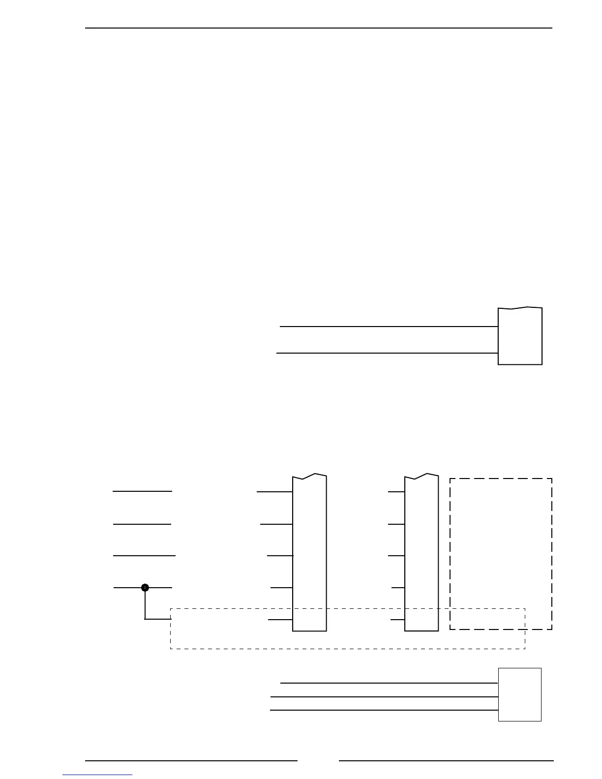
Figure 10. Navistar TGA304/404 Wiring
Note: Refer to Figure 4. TGA 12-Pin Connector
Wiring for power and interlock wire connections.
Voltage Control
Post 2007 MAXXFORCE 7, DT, 9, 10, 11, and 13 Engines
8-Pin
Connector
(Refer to
Figure 5)
Split Shaft Only
ECM Function
Voltage Ref 5V
Signal Return
REM Accelerator
Variable PTO Enable
Transfer Case
Circuit #
(V8)
K95
K95R
K97RPS
K97RVAR
K97SCX
Circuit #
(IBBE)
K92A4
K92A3
K92A5
K92A12
K92A7
Pin 1
Red Wire
Pin 2
B lack Wire
Pin 3
Orange Wire
Pin 8
Brown Wire
X1-27
X1-35
X1-50
X1-60
X1-11
X1-14
X1-6
X1-20
X3-20
X4-6
Circuit #
(I6)
K97FV
K97WA
K99F
K97CC
K97XC
J1939 CAN Bus Control 12VXY
2010 and Newer MAXXFORCE 11 and 13 Engines
C1-47
C1-34
J1939 (–)
J1939 (+)
Pin 5 Black Wire
Pin 4 Red Wire
12-Pin
Connector
(Refer to
Figure 4)
ECM 58-Pin
C1 Connector
12VZA
12VZB
EST
Connector
J1939 CAN (–)
J1939 CAN (Shield)
Pin 5 Black Wire
Pin 12 Yellow Wire
Pin 4 Red Wire
J1939 CAN (+)
Pin E
Pin D
Pin C
12-Pin
Connector
(Refer to
Figure 4)
 Loading...