TGA300 Rev180405
48
FLYBACK DIODE INFORMATION
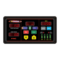
It is good engineering practice to include a yback diode when switching an
inductive load (solenoid coil, relay coil, electric motor winding, etc.). It is recommended
that a yback diode be installed on inductive devices that share a common power
source/ground with a FRC governor.
Typical circuit showing a yback diode
installed across an inductive load.
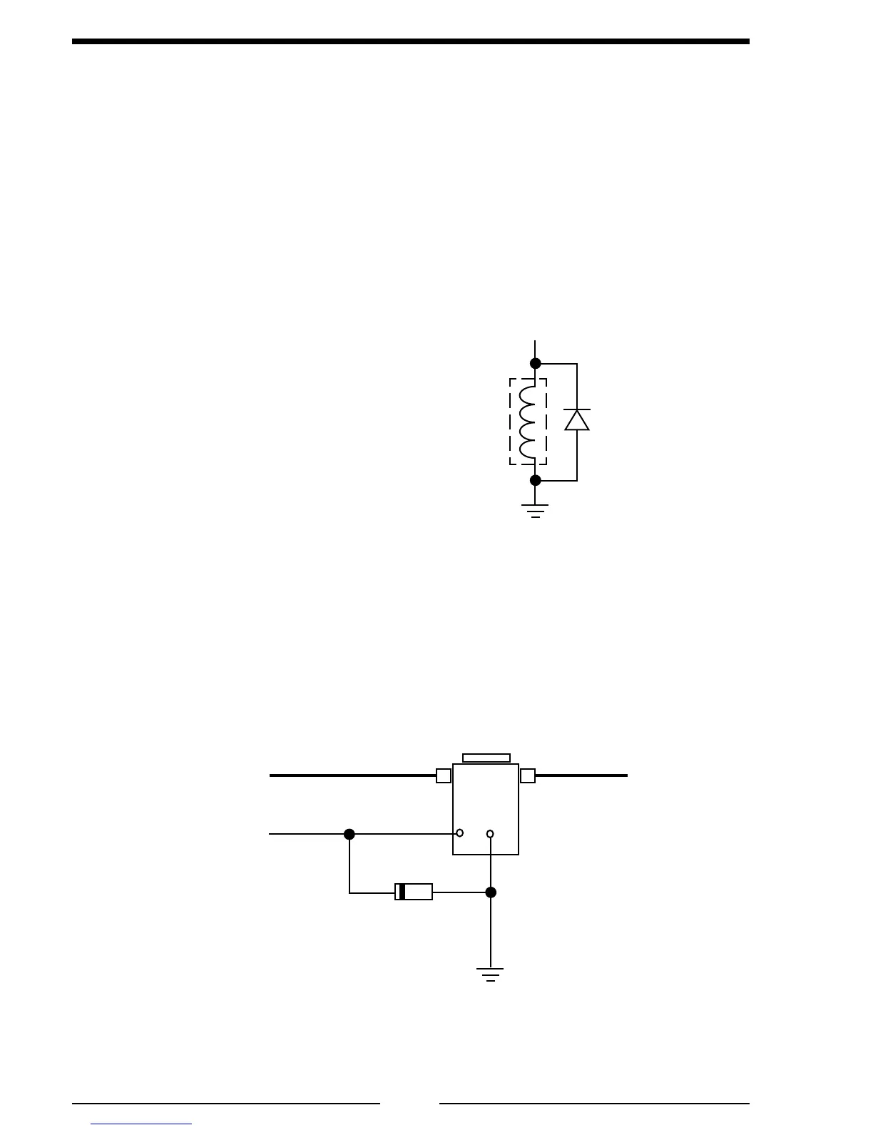
Diagram showing a yback diode connected
on a typical pump primer motor solenoid.
Primer Motor
Solenoid
+12 VDC
Supply
From Primer
Motor Switch
To Primer
Motor
GND
+
–
Diode
Figure 23. Flyback Diode
Diode
Inductive
Load
GND
+V
 Loading...