TGA300 Rev180405
7
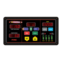
Control Module
The control module is waterproof and uses 10 1/2 by 5 1/2 inches of panel space.
All controls, indicators, and displays are located on the front of the control module.
The TGA300 Series uses push buttons to adjust pressure and RPM settings. The
TGA400 Series uses the FRC hand throttle style control knob to adjust pressure and
RPM settings. (Refer to Controls and Indicators.)
Intake Pressure Sensor
The pressure sensor is mounted on the pump intake manifold. It provides an input
signal to the control module that is proportional to the intake pressure.
Discharge Pressure Sensor
The pressure sensor is mounted on the pump discharge manifold. It provides an
input signal to the control module that is proportional to the discharge pressure.
Audible Alarm Buzzer
A ground is provided at the 8-pin connector pin 7 to activate the buzzer (max
current: 300mA). The buzzer will sound when a fault code becomes activated.
(See Table 3 for the Fault Warning Codes list/descriptions on page 15.)
Cables
There are two standard cables and one optional cable that connect to the control
module. One 8-pin connector and one 12-pin connector. (Refer to Wiring Section.)
High-Idle (Optional)
The governor programming includes a high-idle function. To activate the high-idle
provide a +12 VDC to High-Idle Active Input. (Refer to High-Idle Wiring.).
The high idle is set to 1000 RPM at the factory. (This value will vary depending on
the specic engine.) To adjust this setting refer to High Idle in the Operation Section.
 Loading...