EasyManua.ls Logo

Frecon FR150A Series - User Manual

Frecon FR150A Series
59 pages
Print Icon
To Next Page IconTo Next Page
Loading...
FR150A Series Multifunctional Compact Inverter
- 1 -
PREFACE
Thank you for choosing FRECON developed and produced FR150A series
multifunctional compact inverter.
FR150A Series multifunction compact inverter is a compact, feature-rich, and highly
price-competitive models. Particularly suitable for electronic equipment, food packaging, woodworking,
treadmills and other small power transmission applications. This user manual presents a detailed
description of FR150A series multifunction compact inverter product characterization, structural
features, parameter setting, operation and commissioning, maintenance inspection, and other
contents. Make sure to carefully read the safety precautions before application, and use this product
on the premise that personnel and equipment safety is ensured.
IMPORTANT NOTES
To illustrate the details of some of the products in this manual have outer casing or safety
shields be removed picture .When using this product, please be sure to install a good outer
casing or covering, and in accordance with the contents of the manual operation.
The illustrations this manual for illustration only and may vary with different products you have
ordered.
The company is committed to continuous improvement of products, product features will
continue to upgrade, the information provided is subject to change without notice.
If you are using have questions, please contact our regional agents or our customer service
center. Customer Service Tel 0755 -33067999.
The company's other products please visit our website: .http://www.frecon.com.cn

Table of Contents

Question and Answer IconNeed help?

Do you have a question about the Frecon FR150A Series and is the answer not in the manual?

Summary

Preface

Chapter 1 Product Information

1.1 Nameplate Information

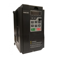
Product's identification label and key specifications.

1.2 Product Model Explanation

Breakdown of the product model numbering system and its meaning.

1.3 Technical Features

Comprehensive list of technical specifications and characteristics for the FR150A series.

1.4 Configuration, Mounting, and Dimensions

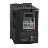
Details on product configuration, mounting instructions, and physical dimensions.

Chapter 2 Wiring and Terminals

2.1 Wiring Diagrams

Visual representations of typical wiring configurations for inverter models.

2.2 Terminal Configuration and Functions

Breakdown of main and control circuit terminals and their specific functions.

Chapter 3 Operation and Display

3.1 Keypad Overview and Functions

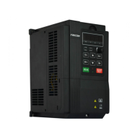
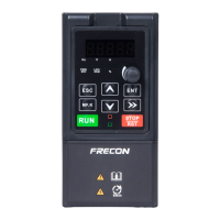
Explanation of the keypad layout, keys, and their operational functions.

3.2 Viewing and Modifying Function Codes

Guide to navigating menus for parameter viewing and changing settings.

3.3 Status Parameters Viewing

How to display and monitor inverter operating status parameters.

3.4 Motor Auto-tuning

Procedure for automatic motor parameter tuning for optimal performance.

3.5 Password Setting

Instructions for setting and managing the inverter's password protection.

3.6 Keypad Lock

Methods for locking and unlocking the keypad to prevent unintended operations.

3.7 Shortcut Menu Description

Explanation of the shortcut menu functionality and its differences.

Chapter 4 Parameter Reference

4.1 LED Display Indicators

Description of the five LED indicators on the keypad and their meanings.

4.2 Standard Function Parameters

Detailed listing and explanation of standard function parameters (F00-F17, F22).

4.3 Pulse Feedback Function

Details on pulse feedback configuration and related parameters (H00).

Chapter 5 Maintenance and Troubleshooting

Troubleshooting Fault Codes

Table of fault codes, their possible causes, and recommended solutions.

Appendix A Modbus Communication Protocol

1. Application Scope & Interface

Defines protocol scope and RS485 physical interface requirements.

2. Protocol Format & Command Codes

Details RTU message format and available command codes.

3. Register Address Allocation

Mapping of function codes to RAM/EEPROM addresses for communication.

4. Command Functions & Status Words

Description of command functions, status words, and error responses.

5. CRC Parity Calculation

Explanation of the CRC parity calculation method used in communication.

Appendix B Braking Resistor

Braking Resistor Configuration

Recommended external braking resistor configurations based on model and load.

Frecon FR150A Series Specifications

General IconGeneral
Efficiency≥90%
Protection LevelIP20
Output Frequency60Hz
Operating Temperature-10°C to +50°C
Storage Temperature-20℃~+60℃
Humidity5% to 95% (non-condensing)

Related product manuals