EasyManua.ls Logo

Frecon FR500A-4T-011G/015PB - User Manual

Default Icon
171 pages
Print Icon
To Next Page IconTo Next Page
Loading...
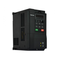
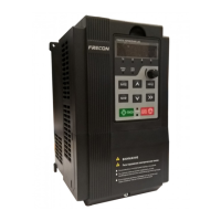
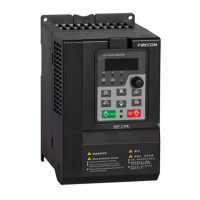
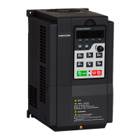
FR500A&FR510A Series Vector Control Inverter
- 1 -
Preface
Thank you for choosing FRECON developed and produced FR500A&FR510A series
vector control inverter.
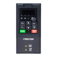
FR500A&FR510A series vector control inverter is mainly positioned as a high-end market for
OEM customers and the specific requirements of fan and pump load applicationsits flexible design,
both embedded SVC and VF control in one, can be widely used for speed control accuracy, torque
response speed, low-frequency output characteristics and other situations with higher requirements.
This user manual supplies a detailed description of FR500A &FR510A series vector control
inverter includes product characterization, structural features, parameter setting, operation and
commissioning, inspection maintenance and other contents. Be sure to carefully read through the
safety precautions before use, and use this product on the premise that personnel and equipment
safety is ensured.
IMPORTANT NOTES
To illustrate the details of the productspictures in this manual based on products with outer
casing or safety cover being removed. When using this product, please be sure to well install
outer casing or covering by the rules, and operating in accordance with the manual contents.
The illustrations this manual for illustration only and may vary with different products you have
ordered.
The company is committed to continuous improvement of products, product features will
continue to upgrade, the information provided is subject to change without notice.
If you are using have questions, please contact our regional agents or our customer service
center. Customer Service Tel 0755 -33067999.
The company's other products please visit our website. http://www.frecon.com.cn

Table of Contents

Questions and Answers

Summary

Safety Precautions

Safety Considerations

Details important safety considerations for the inverter during installation, wiring, and operation.

Precautions

Outlines specific precautions for motor insulation, thermal protection, vibrations, and operating conditions.

Installation and Wiring

Installation Environment

Defines the suitable environmental conditions for installing the inverter.

Installation Direction, Space and Cooling

Specifies installation orientation, required clearances, and cooling considerations.

Configuration of Peripheral Devices

Outlines the standard configuration and selection of peripheral devices.

Wiring way

Describes general wiring principles and recommendations for signal and power cables.

Terminal Configuration

Details the main and control circuit terminal configurations for various models.

Operation and Display

Viewing and Modifying Function Codes

Explains how to navigate the three-level menu to view and modify parameters.

Motor Auto-tuning

Details the procedure for performing motor auto-tuning for optimal performance.

List of Parameter

Standard Function Parameters

Provides a detailed list and description of standard function parameters.

Specification of Parameters

Group F01: Frequency Command

Lists parameters for controlling the frequency command source and settings.

Group F02: Start;Stop Control

Covers parameters for controlling the start, stop, and running direction.

Group F03 Accel;Decel Parameters

Details parameters for acceleration and deceleration time and curves.

Group F08 Parameters of Motor 1

Defines parameters for Motor 1, including type, rating, and electrical characteristics.

Group F09 V;f Control Parameters of Motor 1

Sets V/f control parameters for Motor 1, including curves and compensation.

Group F10 Vector Control Parameters of Motor 1

Configures vector control parameters for Motor 1, including PI gains and limits.

Group F11 Protection Parameters

Defines various protection functions like overcurrent, overvoltage, and overload.

Group F18 Parameters of Motor 2

Defines parameters for Motor 2, similar to Motor 1 parameters.

Group F19 V;f Control Parameters of Motor 2

Sets V/f control parameters for Motor 2, including curves and compensation.

Group F20 Vector Control Parameters of Motor 2

Configures vector control parameters for Motor 2, including PI gains and limits.

Maintenance and Troubleshooting

Inspection

Details daily and regular inspection procedures for the inverter and its components.

Maintenance

Provides guidance on maintenance tasks, including fan replacement and other device upkeep.

Braking Resistor

PG Card

Frecon FR500A-4T-011G/015PB Specifications

General IconGeneral
ModelFR500A-4T-011G/015PB
CategoryInverter
Input Phase3-Phase
Output Power11kW/15HP
Control MethodV/F control, sensorless vector control
Cooling MethodForced air cooling
Enclosure RatingIP20
Input Voltage380-480V
Output Voltage0-Input Voltage
Frequency Range0-400Hz
Protection FeaturesOvercurrent, Overvoltage, Undervoltage, Overheating, Short Circuit
Communication InterfaceRS485

Related product manuals