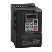
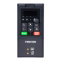
FR200 Series Vector control inverter
- 1 -
FR200 series inverters fast installation and commissioning guide
Step 1. Checking the inverter model No.
FR200□-4T-7.5G/011PB
Master series code of
Product:
FR200: Vector control
inverter
Input voltage:
2: 220V(-15%~+30%)
4: 380V(-15%~+30%)
Input voltage phases:
S:Single-phase
T:Three-phase
Industry-specific series
code:
None:Standard Machine
A~Z:Industry-specific
retention
Brake unit:
None: No Braking Unit
B: Built-in brake unit(30kW
following built,37 ~ 75kW optional
built,No built above 90kW)
Adaptable Motor (kW)And Type of
Motor:7.5G:7.5kW(General type)
011P:11kW(Fan pump type)
Figure 1 Produce Model No. Naming Rule
Step 2. Wirings
By step 1 to check and confirm that the purchased inverter is what user need, and
then wirings as below:
1. Main circuit wiring
L1
L2
L3
U
V
W
MCCB
M
Inverter
Power
(+) PB
Braking Resistor(Optional spares)
Figure 2 Main Circuit Wirings
Designation and function of terminals.
AC power input terminals for connecting to 3-phase AC380V power
supply.
AC output terminals of inverter for connecting to 3-phase induction
motor.
Positive and negative terminals of internal DC bus.
Positive and negative terminals of internal DC bus. Connecting
terminals of braking resistor. One end connected to + and the other to
PB.
2. Control circuit wirings
Different control circuit wirings for different applications, for FRECON product
quick-menu, here take some normal-used wirings as example below:
