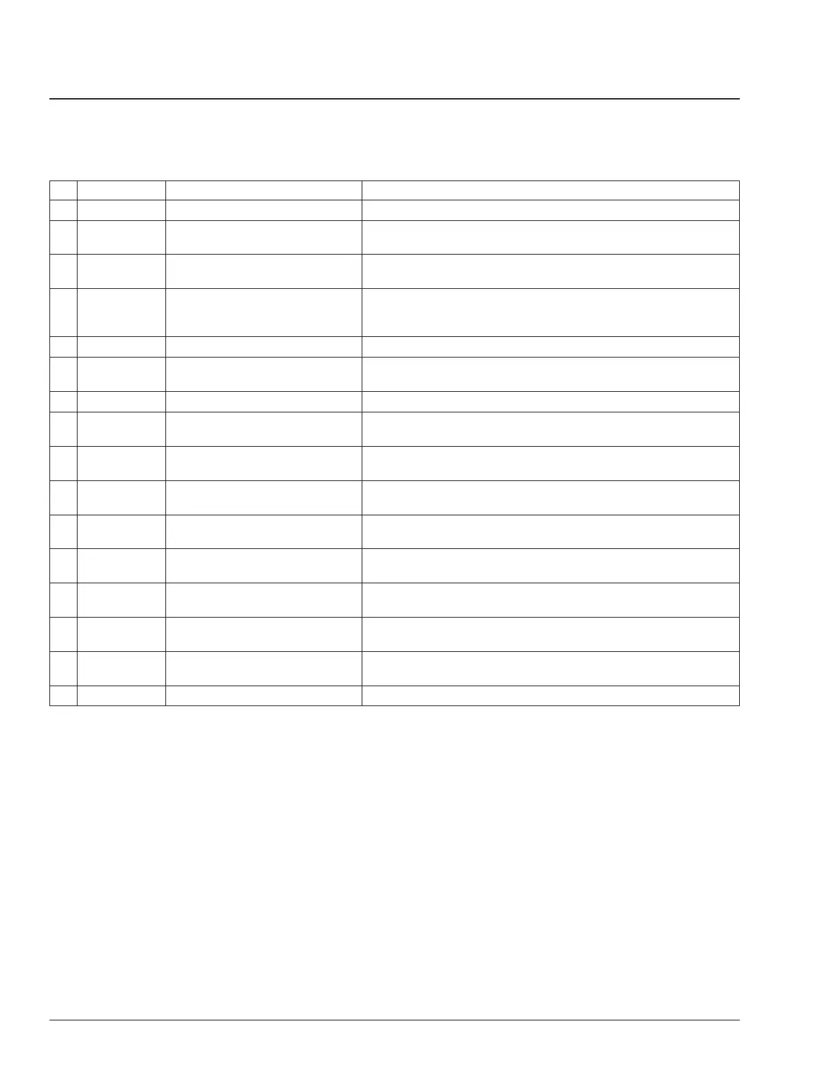
No. MOP No. Component Remarks
*
8 33–03 Tie Rod Two grease fittings; one on each end of tie rod.
9 33–01 Knuckle Pins Two grease fittings; one on top, one on bottom of knuckle pin.
Lubricate both sides of axle.
10 25–01 Clutch Release Bearing and
Release Cross-Shaft
One grease fitting on bottom of release bearing. Two grease
fittings on release cross-shaft.
11 26–01, 26–02,
26–05, 26–06,
26–08, 26–10
Transmission Check fluid level; add fluid, if low (26–01). Change fluid (26–02,
26–05, 26–06, 26–08, or 26–10), when required.
12 41–02 Driveline U-Joints and Slip-Joints One grease fitting for each U-joint, and one for each slip-joint.
13 72–01 Door Hinges, Latches, and
Weatherstrips
Lubricate all door hinges, latches, and weatherstrips on the cab.
14 15–01 Batteries Clean and lubricate if corrosion is present.
15 42–19 Air Reservoir Automatic Drain
Valves
Disassemble, clean, inspect, and lubricate automatic drain valves.
16 32–02 Suspension Spring Pin Lubricate on both sides of vehicle; one grease fitting for each
spring pin.
17 32–02 Equalizer
†
One grease fitting on each equalizer; lubricate both sides of
vehicle.
18 35–04, 35–05 Two-Speed-Axle Shift Unit
†
Check oil level; add oil if low (35–04). Change oil (35–05) when
required.
19 35–01, 35–03 Rear Axle Check fluid level; add fluid, if low (35–01). Change fluid, when
required (35–03).
20 42–11, 42–13,
42–24, 42–26
Slack Adjusters, Rear Axle Lubricate slack adjusters on both sides of each rear axle, one
grease fitting for each slack adjuster.
21 42–10 Camshaft Brackets, Rear Axle Lubricate camshafts on both sides of each rear axle; one grease
fitting for each camshaft bracket.
22 31–03 Fifth Wheel
†
Inspect the fifth wheel, then lubricate top plate and all moving
parts.
23 42–03 Air Valves
‡
Disassemble, clean, and lubricate all air valves.
*
Intervals and procedures are included in the "Maintenance Operations Tables" and the specific groups.
†
Not shown in illustration.
‡
Air valves are located throughout the vehicle; inside the cab and on the chassis.
Table 17, Lubrication Table for All Models but FL112
See Fig. 2 for lubrication points (FL112 models only).
General Information00
Lubrication Tables: 00–18
Business Class Trucks Maintenance Manual, February 200400/28