If the oil is acceptable, check the oil level. If it is not
full, as shown in Fig. 9, fill it to the bottom of the
vent plug hole with approved lubricant. For approved
lubricants, see
Table 1.
Lubricant Specifications, Over-the-Road Service
Applications
Lubricant Type
Lubricant SAE
Viscosity Grade
Synthetic Drive Axle Lubricants or
Equivalent with SAE Specification
J2360 or Military Specification MIL-L-
2105E
75W-90
Table 1, Lubricant Specifications, Over-the-Road
Service Applications
33–06 All-Axle Alignment
Check
Drive Axle Alignment Checking
Check the axle alignment, parallelism, and thrust
angle measurements for the rear drive axles. Use the
applicable procedure and specifications in Group 35
of the Business Class M2 Plus Workshop Manual.
Toe-In Inspection
For vehicle alignment to be accurate, the shop floor
must be level in every direction. The turn plates for
the front wheels must rotate freely without friction,
and the alignment equipment must be calibrated
every three months by a qualified technician from the
equipment manufacturer. Freightliner dealers must
have proof of this calibration history.
1. Apply the parking brakes and chock the rear
tires.
2. Raise the front of the vehicle until the tires clear
the ground. Place safety stands under the axle.
3. Using spray paint or a piece of chalk, mark the
entire center rib of each front tire.
4. Place a scribe or pointed instrument against the
marked center rib of each tire, and turn the tires.
The scribe must be held firmly in place so that a
single straight line is scribed all the way around
each front tire.
5. Place a turn-plate or turntable under both front
tires. Remove the safety stands and lower the
vehicle. Remove the lock-pins from the gauges;
make sure the tires are exactly straight ahead.
NOTE: If turn-plates or turntables are not
available, lower the vehicle. Remove the chocks
from the rear tires and release the parking
brakes. Move the vehicle backward, then
forward about six feet (two meters).
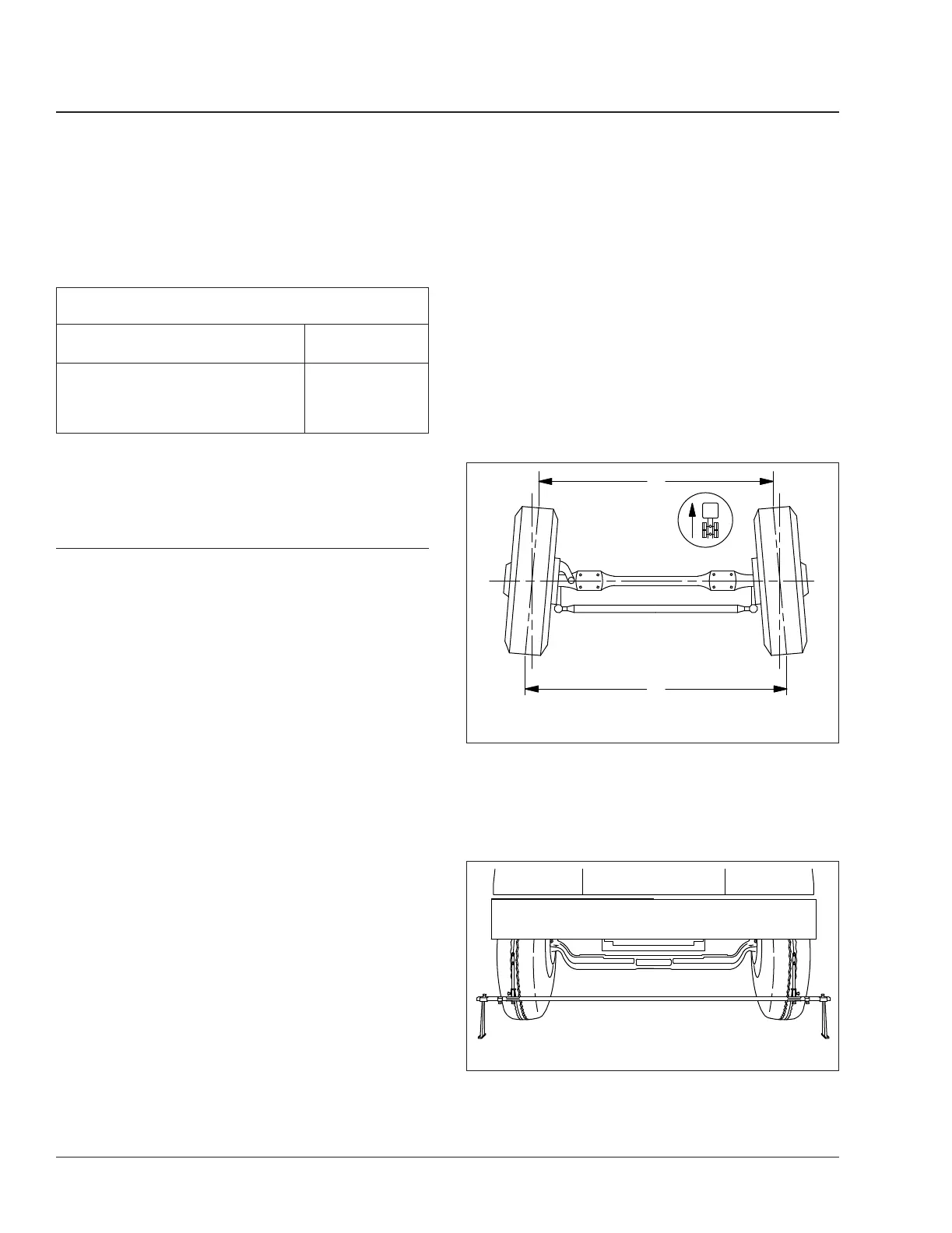
6. Place a trammel bar at the rear of the front tires;
locate the trammel pointers at spindle height,
and adjust the pointers to line up with the scribe
lines on the center ribs of the front tires. See
Fig. 10. Lock in place. Check that the scale is
set on zero.
7. Place the trammel bar at the front of the tires, as
shown in
Fig. 11, and adjust the scale end so
that the pointers line up with the scribe lines.
See
Fig. 12.
f330082a10/05/2016
A
B
NOTE: B minus A equals toe-in.
Fig. 10, Wheel Toe-In (overhead view)
f330014a10/05/2016
Fig. 11, Trammel Bar Positioning
Front Axle33
Business Class M2 Plus Maintenance Manual, 02/10/202333/6