QUANTUM
™
LX CONDENSER/VESSEL CONTROL PANEL
MAINTENANCE
090.560-M (MAY 2016)
Page 16
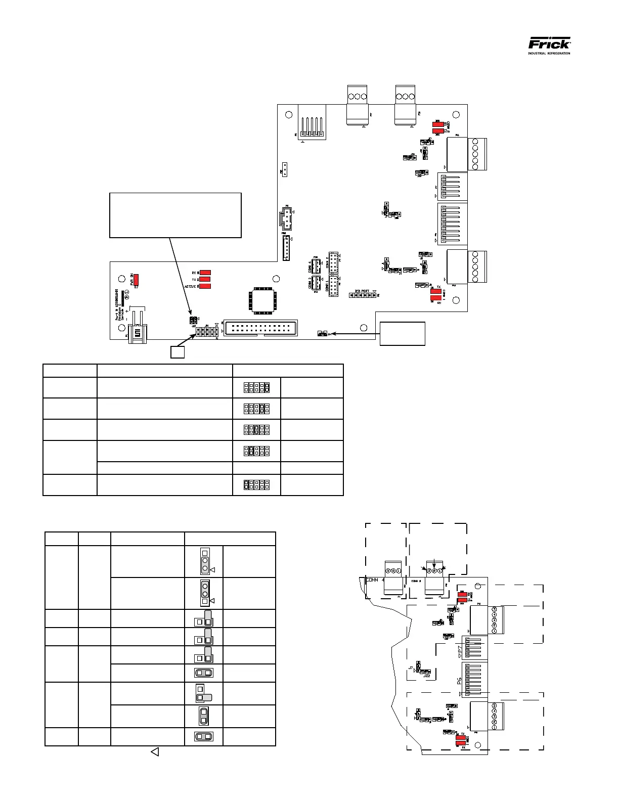
Q5 INTERFACE BOARD
P1
Power Connector
Do Not
Remove J14
Baud Rate Jumpers
J15 Not Installed = 19200 (Default)
J15 Pins 1-2 Installed = 38400
J15 Pins 3-4 Installed = 56K
J15 Pins 1-2 and 3-4 Installed = 115K
COMM
4
COMM
3
COMM
2
COMM
1
JP1
NOTE: Jumper 7-8 is normally the only jumper that would be installed (for a DG81 display only)
COMMS 1 & 2 JUMPER SETTINGS
(Comms 3 and 4 have no jumpers)
COMMS 1-4 PINOUTS AND JUMPER LOCATIONS
Comm 1 Comm 2 Function Jumper Setting
J1 J7
RS-422 (4-Wire)
Default
3
1
1 - 2 Closed
RS-485
(2-Wire)
2
1
2 - 3 Closed
J2 J13
Pull Down
Default
1 Pin Only
J3 J16
Pull Up
Default
1 Pin Only
J5 J17
RS-422
Default
1 Pin Only
RS-485 1 - 2 Closed
J6 J18
RS-422
Default
1 Pin Only
RS-485
1 - 2 Closed
J4 J22
High Speed Target
Default
1 - 2 Closed
NOTE: The triangle symbol (
) denotes Pin 1 on connectors.
COMM-1
(P10)
RS-422
GND
+TX
-TX
+RX
-RX
RS-485
N/C
N/C
GND
+TX/+RX
-TX/-RX
COMM-2
(P11)
RS-422
GND
+TX
-TX
+RX
-RX
RS-485
N/C
N/C
GND
+TX/+RX
-TX/-RX
COMM-4
(P17)
RS-485
(RESERVED)
COMM-3
(P16)
RS-485
GND
+TX/+RX
-TX/-RX
Jumper JP1 Function Jumper Setting
1 - 2 Not Used Not Installed
3 - 4 Reformat E
2
Prom Installed
5 - 6 Erase Setpoints (at boot-up) Installed
7 - 8
DG81 Display Installed (default)
Installed
DG61 Display Installed Not Installed
9 - 10 Disable Watchdog
Installed