QUANTUM
™
LX CONDENSER/VESSEL CONTROL PANEL
MAINTENANCE
090.560-M (MAY 2016)
Page 29
Q4 SPECIFIC INFORMATION
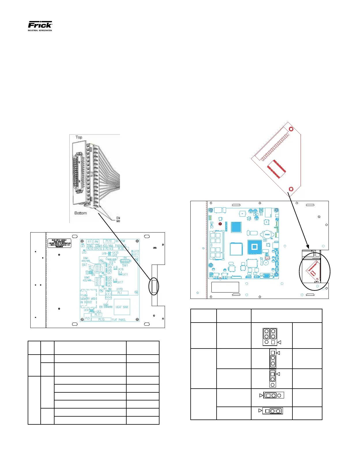
The end of the display cable that plugs into the display
has an adapter connector plugged into it, which adapts
the display cable to the display. When unplugging the dis-
play cable from the back of the display, it is possible that
the display cable connector may separate from the display
adapter connector. If this occurs, refer to the following
drawing to ensure proper connector orientation when
plugging the display cable back into the display:
With the display connector held as shown, orient the dis-
play harness to plug onto the back pins with the 2 empty
wire holes oriented down toward the bottom as shown:
Q4 Motherboard Display Jumpers (links)
Link
#
Link
Pos.
Description Frick P/N
LK3
A +5V Backlight Voltage (Not used) N/A
B*
+12V Backlight Voltage (All
Displays)
N/A
LK4
A
+5V LCD Supply Samsung 333Q0001180
+5V LCD Supply NEC 333Q0001494
+5V LCD Supply Sharp 333Q0001581
+5V LCD Supply Sharp DG61 639C0132H01
B*
+3.3V LCD Supply LG Philips 649C1078H01
+3.3V LCD Supply Sharp DG81 639C0144H01
* standard setting
(Refer to “Q4 Board Settings” for location of jumpers)
Q5 SPECIFIC INFORMATION
The display for the Q5 utilizes a “bat wing” adapter board
that plugs into the display connector, and accepts the dis-
play harness from the Q5. This adapter board is keyed so
that it cannot be plugged in wrong. The display harness
is also keyed, so that its orientation is assured. To aide
in accessing this “bat wing” adapter, the Interface board
should be removed. A drawing of the “bat wing” adapter
and its location is shown here (with Interface board re-
moved) NOTE: Verify the setting of the JLVDS3 (shown
below), especially when replacing a CCFL display, with
an LED display (DG81):
Q5 Motherboard Display Jumpers (links)
Jumper
Title
Function Jumper Setting
CN1000
(LCD
Resolution
Selector)
18-bit
640x480
(default)
6
4
2
3
3-5 Closed
&
4-6 Closed
JLVDS2
(Backlight
Level
Selector)
0– 5V
(default)
2-3 Closed
0 – 2.5V
3
1-2 Closed
JLVDS3
(Backlight
Control
Mode)
Voltage Mode
(CCFL)
(default)
1-2 Closed
PWM Mode
(LED - DG81)
2-3 Closed
(Refer to “Q5 Board Settings” for location of jumpers)