RWB II ROTARY SCREW COMPRESSOR UNITS
INSTALLATION
S70-210 IOM
Page 10
OIL HEATER(S)
Standard units are equipped with 2 or 3 500 or 1000 watt oil
heaters, providing sufficient heat to maintain the oil tempera-
ture for most indoor applications during shutdown cycles to
permit safe start-up. Should additional heating capacity be
required because of low ambient, contact Frick. The heater(s)
is energized only when the unit is not in operation.
Do not energize the heater(s) when
there is no oil in the unit, the heat-
er(s) will burn out. The oil heater(s)
will be energized whenever 120 volt control power is
applied to the unit and the compressor is not running,
unless the 16 amp circuit breaker in the micro enclosure
is turned off.
OIL FILTER(S)
Use of filter elements other than
Frick may cause warranty claim
may to be denied.
The oil filter(s) and coalescer filter element(s) shipped with
the unit are best suited to ensure proper filtration and opera-
tion of the system.
LIQUID INJECTION OIL COOLING
The liquid injection system provided on the unit is self-con-
tained but requires the connection of the liquid line sized as
shown in the table and careful insertion of the expansion valve
bulb into the thermowell provided in the separator.
There are two forms of liquid injection cooling, balanced
pressure and temperature/pressure-compensated.
• In the TXV balance pressure valve, the high-pressure
conection is made through the regulator to the external port
on the liquid injection valve to control oil temperature.
• In the Jordan temperature pressure compensated
valve, no external high-pressure connection is required.
The thermal bulb supplies all necessary pressure to the
valve for increasing or decreasing the required amount
of refrigerant.
NOTE: For booster applications the high pressure gas
connection must be taken from a high side source (high
stage compressor discharge). This should be a 3/8" line
connected into the solenoid valve provided. This gas is
required by the expansion valve external port to control
oil temperature.
It is IMPERATIVE that an uninterrupted supply of high pres-
sure liquid refrigerant be provided to the injection system at
all times. Two items of EXTREME IMPORTANCE are the
design of the receiver/liquid injection supply and the size of
the liquid line.
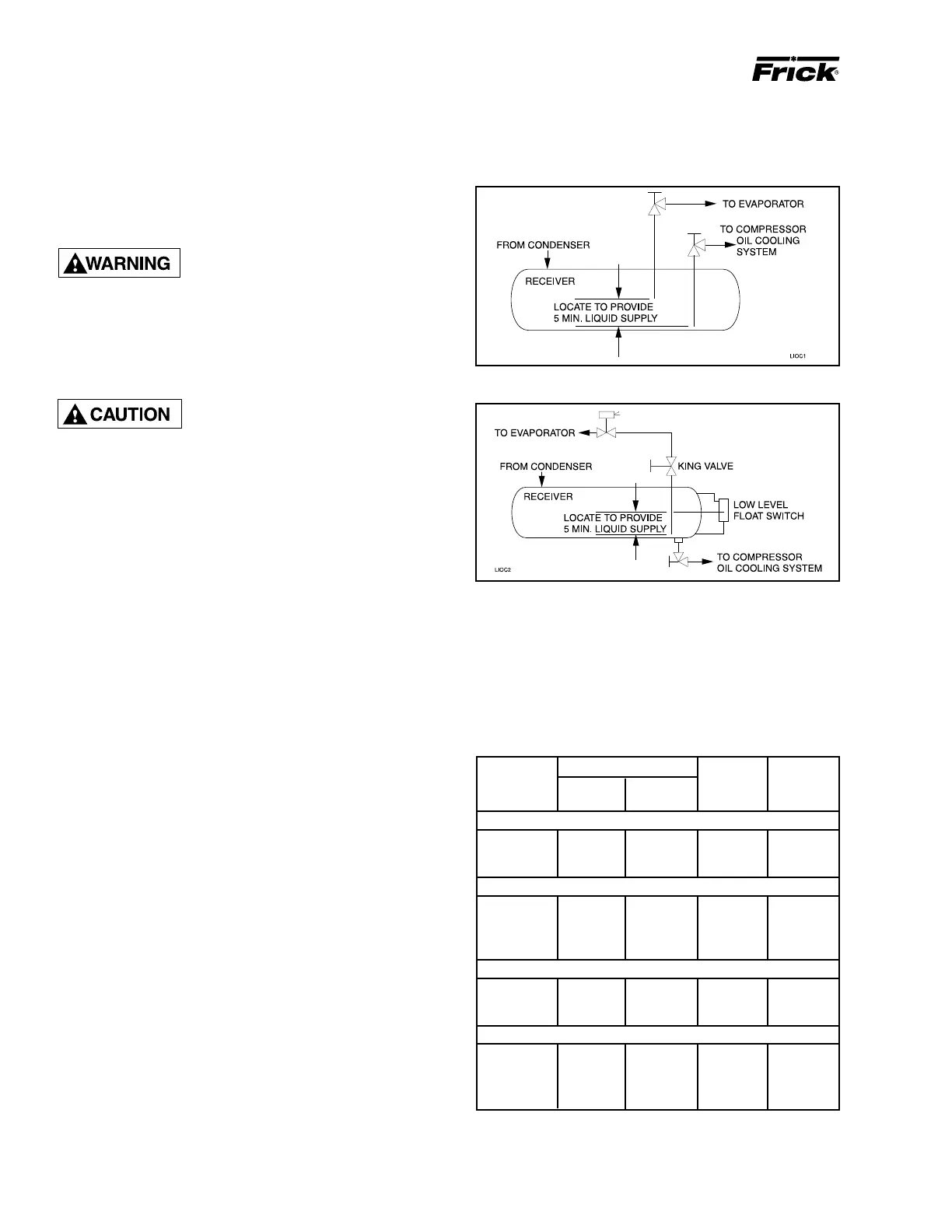
It is recommended that the receiver be oversized sufficiently
to retain a 5 minute supply of refrigerant for oil cooling. The
evaporator supply must be secondary to this consideration.
Two methods of accomplishing this are shown.
The Dual Dip Tube method uses two dip tubes in the receiver.
The liquid injection tube is below the evaporator tube to en-
sure continued oil cooling when the receiver level is low.
LIQUID LINE SIZES/RECEIVER VOLUME
Liquid line sizes and the additional receiver volume (quantity
of refrigerant required for 5 minutes of liquid injection oil
cooling) are given in the following table:
LIQUID LINE SIZE and RECEIVER VOLUME
Figure 7 - Dual Dip Tube Method
Figure 8 - LEVEL CONTROL METHOD
The Level Control method utilizes a float level control on
the receiver to close a solenoid valve feeding the evapora-
tor when the liquid falls below that amount necessary for 5
minutes of liquid injection oil cooling.
* Based on 100 foot liquid line. For longer runs, increase line
size accordingly.
LINE SIZE* POUND LIQUID
RWF II SCH 80 OD PER VOLUME
MODEL PIPE TUBING 5 MIN. CU FT
R-717 HIGH STAGE*
496 2 – 310 8.5
676 2 – 420 11.5
856 2 – 650 18
R-717 BOOSTER*
496 1 – 50 1.5
676 1 – 70 2.0
856 1-1/4 – 125 3.5
1080 1-1/4 – 155 4.4
R-22 HIGH STAGE*
496 2-1/2 2-5/8 1,300 18.0
676 3 2-5/8 1,780 25.0
856 3 2-5/8 1,960 27.0
R-22 BOOSTER*
496 1-1/4 1-1/8 114 1.6
676 1-1/4 1-1/8 156 2.2
856 1-1/4 1-1/8 266 3.7
1080 1-1/4 1-1/8 335 4.6

 Loading...