RWB II ROTARY SCREW COMPRESSOR UNITS
INSTALLATION
S70-210 IOM
Page 14
For refrigeration plants using a Packaged Refrigerant Recir-
culation (PRR) unit and a direct expansion (DX) economizer
system it is necessary to operate the liquid feed solenoid on
the PRR unit and the liquid feed solenoid on the DX vessel
off of a common signal to avoid liquid overfeed on the DX
economizer system.
ECONOMIZER LOAD BALANCING
The most energy efficient manner to operate an economizer
system, when using multiple compressors on a common
economizer vessel, is to take as much of the flash gas as
possible to the compressors that are fully loaded. This can
be done in at least two ways.
1. Use the economizer output from the microprocessor to
turn off a solenoid, or to actuate the electric shutoff option
on a back-pressure regulator, based on percent of slide valve
travel. This will direct all the flash vapor to the other loaded
compressors.
2. A dual-setpoint back-pressure regulator valve can be used
in each of the individual economizer vapor lines. When a com-
pressor is running near full load, the BPR valve will operate
on the desired setpoint, or basically wide open, to minimize
pressure drop in the line. When one compressor unloads
below the slide valve position where the economizer output
on the microprocessor turns on, the dual-setpoint feature of
the regulator can be actuated by this output to control the
pressure, on the vessel side of the regulator, to be a few psi
higher. Consequently, the flash gas will be sent to the loaded
compressors first, until they can’t handle all the vapor and
the pressure in the vessel starts to rise. Then, some of the
vapor will go to the unloaded compressor to help maintain
the vessel at the desired pressure. An example of a back-
pressure regulator with electric shutoff and the dual-setpoint
feature is an R/S A4ADS.
ELECTRICAL
NOTE: Before beginning electrical installation, read
the instructions in the section "Proper Installation of
Electronic Equipment".
RWB II units are supplied with a QUANTUM
™
control system.
Care must be taken that the controls are not exposed to physi-
cal damage during handling, storage, and installation. The
microprocessor enclosure cover must be kept tightly closed
to prevent moisture and foreign matter from entering.
All customer connections are
made in the Quantum control panel
mounted on the unit. This is the
ONLY electrical enclosure and should be kept tightly
closed whenever work is not being done inside.
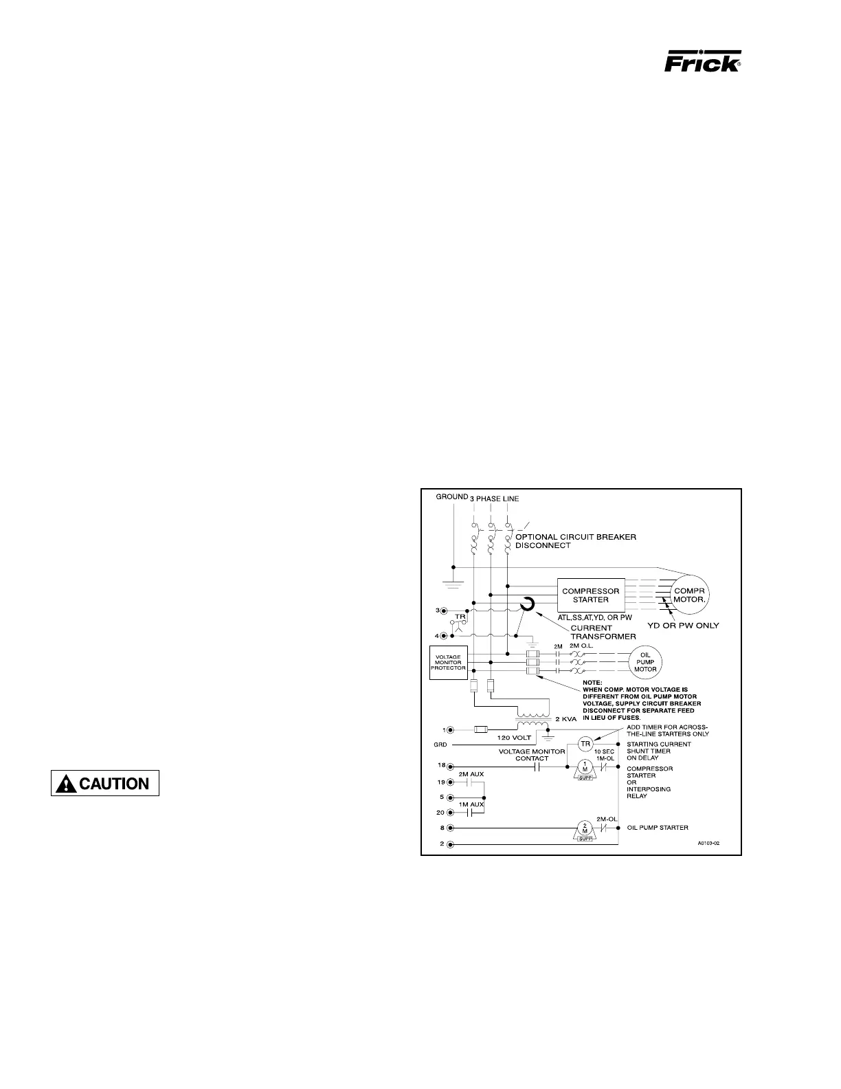
MOTOR STARTER PACKAGE
Motor starter and interlock wiring requirements are shown in
the wiring diagram above. All the equipment shown is sup-
plied by the installer unless a starter package is purchased
from Frick. Starter packages should consist of:
1. The compressor motor starter of the specified HP and
voltage for the starting method specified (across-the-line,
autotransformer, wye-delta, or solid-state).
NOTE: If starting methods other than across-the-line are
desired, a motor/compressor torque analysis must be
done to ensure that sufficient starting torque is available,
particularly in booster applications. Contact FRICK if
assistance is required.
2. If specified, the starter package can be supplied as a
combination starter with circuit breaker disconnect. However,
the motor overcurrent protection/disconnection device can
be applied by others, usually as a part of an electrical power
distribution board.
3. The oil pump starter with fuses, or in the case where the
compressor motor is a different voltage from the oil pump
motor, with a circuit breaker disconnect suitable for separate
power feed.
4. A 2.0 KVA control power transformer (CPT) to supply 120
volt control power to the microprocessor control system and
separator oil heaters is included. If environmental conditions
require more than the usual two 500 watt oil heaters, an ap-
propriately oversized control transformer will be required. If
frequent power fluctuations are anticipated or extremely noisy
power lines are encountered, a regulating control transformer
should be considered. Contact FRICK for assistance.
5. For customer-supplied across-the-line starters, a shunt-
ing devicemust be installed across the Current Transformer
(terminals 3 & 4).
If the shunting device is not installed, the SBC board may
be severly damaged at start-up (see Figure 16).
Figure 16 - Starter Wiring Diagram
6. The compressor motor Current Transformer (CT) is in-
stalled on any one phase of the compressor leads.
NOTE: The CT must see all the current of any one phase,
therefore in wye-delta applications BOTH leads of any
one phase must pass through the CT.
7. One each normally open compressor motor and oil pump
motor starter auxiliary contact should be supplied and in
addition to the compressor and oil pump motor starter coils,
the CT and CPT secondaries wired as shown on the starter

 Loading...