RWB II ROTARY SCREW COMPRESSOR UNITS
OPERATION
S70-210 IOM
Page 18
COMPRESSOR HYDRAULIC SYSTEM
The compressor hydraulic system moves the movable slide
valve (MSV) to load and unload the compressor. It also moves
the movable slide stop (MSS) to increase or decrease the
compressor’s volume ratio (Vi).
The hydraulic cylinder located at the inlet end of the TDS
compressor serves a dual purpose. It is separated by a fixed
bulkhead into two sections. The movable slide valve (MSV)
section is to the left of the bulkhead and the movable slide
stop (MSS) to the right. Both sections are considered double
acting hydraulic cylinders as oil pressure moves the pistons
in either direction.
Both sections are controlled by double-acting, four-way
solenoid valves which are actuated when a signal from the
appropriate microprocessor output energizes the solenoid
valve. See Figures 21 and 22.
Compressor Loading: The compressor loads when MSV
solenoid YY2 is energized and oil flows from the oil manifold
through valve ports P and B to cylinder port SC-2 and enters
the load side of the cylinder. Simultaneously, oil contained in
the unload side of the cylinder flows out cylinder port SC-1
through valve ports A and T to compressor closed thread
port.
Compressor Unloading: The compressor unloads when
MSV solenoid YY1 is energized and oil flows from the oil
manifold through valve ports P and A to cylinder port SC-1
and enters the unload side of the cylinder. Simultaneously, oil
contained in the load side of the cylinder flows out compres-
sor port SC-2 through valve ports B and T to compressor
closed thread port.
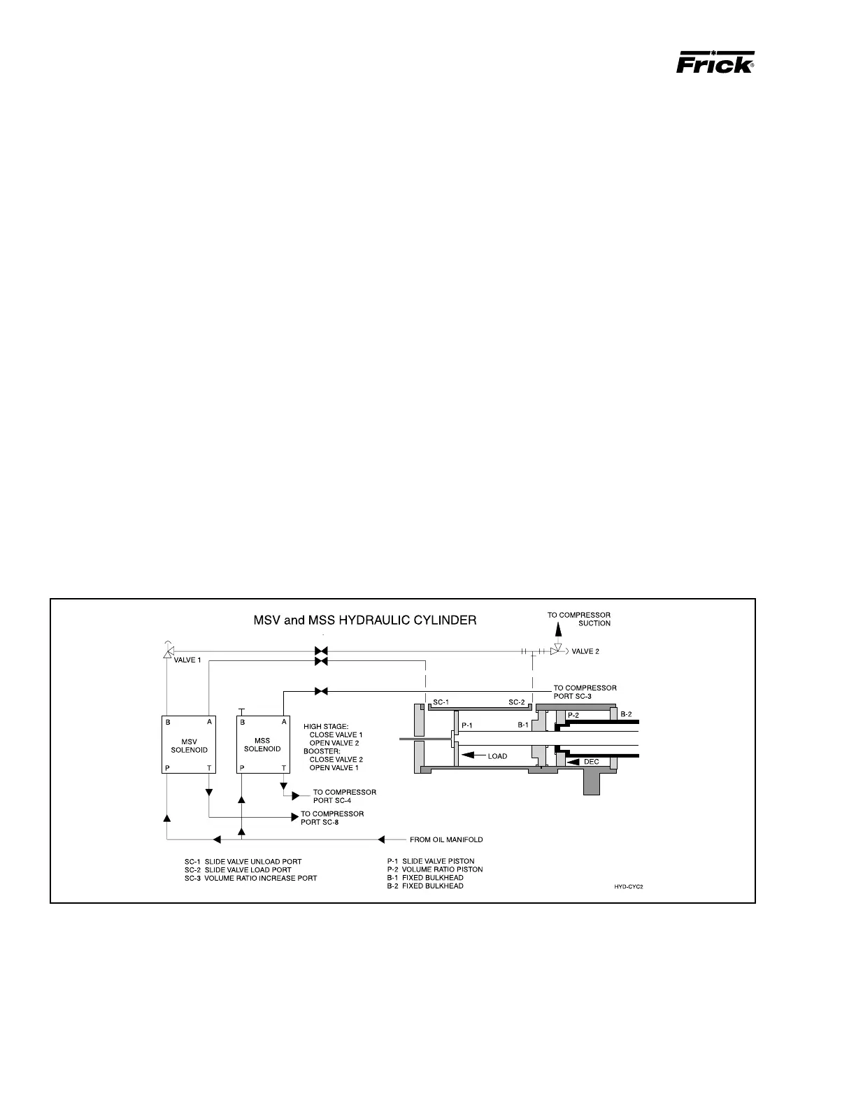
NOTE: High Stage Operation: An alternative piping ar-
rangement has been provided to increase slide valve
response time during high stage operation.
Higher operating pressures will slow the compressor unload-
ing response time. Unloading response time can be increased
by closing valve 1 (oil manifold pressure) and opening valve
2 to compressor suction pressure. See illustrations. NEVER
OPEN VALVE 1 AND VALVE 2 AT THE SAME TIME DUR-
ING COMPRESSOR OPERATION.
VOLUMIZER® VOLUME RATIO CONTROL
Vi Increase
The volume ratio Vi is increased when the MSS solenoid
valve YY3 is energized and oil flows from oil manifold through
valve ports P and A to compressor port SC-3, enters the
increase side of the cylinder and overcomes the decrease
spring tension.
Vi Decrease
The volume ratio Vi is decreased when the MSS solenoid
valve YY4 is energized and oil flows from the cylinder through
compressor port SC-3, through valve ports A and T, to com-
pressor Port SC-4.
Figure 21

 Loading...