RWB II ROTARY SCREW COMPRESSOR UNITS
INSTALLATION
S70-210 IOM
Page 11
WATER-COOLED OIL COOLING (OPTIONAL)
The plate and shell type water-cooled oil cooler is mounted
on the unit complete with all oil piping. The customer must
supply adequate water connections. Determine the size of the
water-cooled oil cooler supplied with the unit, as outlined on
the Frick P&I diagram and arrangement drawings. The water
supply must be sufficient to meet the required flow.
Frick recommends a closed-loop system for the waterside
of the oil cooler. Careful attention to water treatment is es-
sential to ensure adequate life of the cooler if cooling tower
water is used. It is imperative that the condition of cool-
ing water and closed-loop fluids be analyzed regularly
and as necessary and maintained at a pH of 7.4, but not
less than 6.0 for proper heat exchanger life. After initial
start-up of the compressor package, the strainer at the inlet
of the oil cooler should be cleaned several times in the first
24 hours of operation.
In some applications, the plate and shell oil cooler may be
subjected to severe water conditions, including high tem-
perature and/or hard water conditions. This causes accel-
erated scaling rates which will penalize the performance of
the heat exchanger. A chemical cleaning process will extend
the life of the Plate and Shell heat exchanger. It is important
to establish regular cleaning schedules.
Cleaning: A 3% solution of Phosphoric or Oxalic Acid is
recommended. Other cleaning solutions can be obtained from
your local distributor, but they must be suitable for stainless
steel. The oil cooler may be cleaned in place by back flushing
with recommended solution for approximately 30 minutes.
After back flushing, rinse the heat exchanger with fresh water
to remove any remaining cleaning solution.
TABLE 2 - OIL COOLER DATA
TYP COOLER CONNECTION
RWF II MODEL DIA PLATES INLET OUTLET
496 - 676 Hi Stage 24 in. 188 4 in. 5 in.
496 - 856 Booster 24 in. 72 3 in. 3 in.
1080 Booster 24 in. 136 4 in. 5 in.
2. A shell and tube oil cooler with:
Shell Side: Oil 400 lb design
Tube Side: Refrigerant 400 lb design
Due to the many variations in refrigeration system design
and physical layout, several systems for assuring the above
criteria are possible.
SYSTEM OPERATION - Liquid refrigerant fills the cooler
tube side up to the Thermosyphon receiver liquid level
(Figure 9).
Figure 9
Hot oil (above the liquid temperature) flowing through the
cooler will cause some of the refrigerant to boil and vaporize
in the tubes. The vapor rises in the return line. The density of
the refrigerant liquid/vapor mixture in the return line is consider-
ably less than the density of the liquid in the supply line. This
imbalance provides a differential pressure that sustains a flow
condition to the oil cooler. This relationship involves:
1. Liquid height above the cooler.
2. Oil heat of rejection.
3. Cooler size and piping pressure drops.
Current thermosyphon systems are using single-pass oil
coolers and flow rates based on 3:1 overfeed.
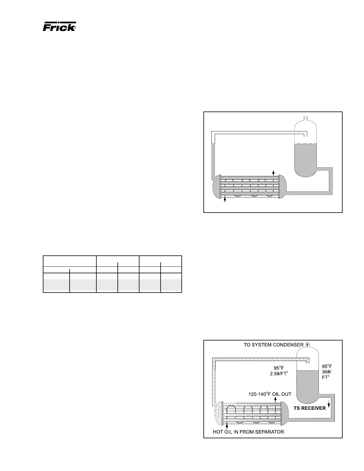
The liquid/vapor returned from the cooler is separated in
the receiver. The vapor is vented to the condenser inlet and
need only be reliquified since it is still at condenser pressure
(Figure 10).
HOT OIL IN FROM SEPARATOR
120-140 F OIL OU
T
O
TO SYSTEM CONDENSER
95
F
36#/FT
O
3
95 F
36#/
FT
O
3
TS RECEIVER
THERMOSYPHON OIL COOLING (OPTIONAL)
Thermosyphon oil cooling is an economical, effective method
for cooling oil on screw compressor units. Thermosyphon
cooling utilizes liquid refrigerant at condenser pressure and
temperature which is partially vaporized at the condenser
temperature in a shell and tube vessel cooling the oil. The
vapor, at condensing pressure, is vented to the condenser
inlet and reliquified. This method is the most cost effective
of all currently applied cooling systems since no compressor
capacity is lost or compressor power penalties incurred. The
vapor from the cooler need only be condensed, not com-
pressed. Refrigerant flow to the cooler is automatic, driven
by the thermosyphon principle and cooling flow increases
as the oil inlet temperature rises.
EQUIPMENT - The basic equipment required for a ther-
mosyphon system consists of:
1. A source of liquid refrigerant at condensing pressure and
temperature located in close proximity to the unit to mini-
mize piping pressure drop. The liquid level in the refrigerant
source must be 6 to 8 feet minimum above the center of the
oil cooler.
Figure 10

 Loading...