RWB II ROTARY SCREW COMPRESSOR UNITS
INSTALLATION
S70-210 IOM
Page 12
OIL TEMPERATURE CONTROL - Oil temperature will gen-
erally run about 15 - 35°F above condensing temperature.
In many cases, an oil temperature control is not required if
condensing temperature is above 65°F as oil temperature
can be allowed to float with condenser temperature.
Condensing Temperature: 65°F - 105°F
Oil Temperature: 80°F - 140°F
INSTALLATION - The shell and tube-type thermosyphon oil
cooler with oil-side piping and a thermostatically controlled
mixing valve (if ordered) are factory mounted and piped. The
customer must supply and install all piping and equipment
located outside of the shaded area on the piping diagram
with consideration given to the following:
1. The refrigerant source, thermosyphon or system receiver,
should be in close proximity to the unit to minimize piping
pressure drop.
2. The liquid level in the refrigerant source must be 6 to 8
feet minimum above the center of the oil cooler.
3. A safety valve should be installed if refrigerant isolation
valves are used for the oil cooler.
TSOC AND WCOC OIL SIDE SAFETY RELIEF - Compres-
sor units assembled after January 1995, which have valves
in the oil piping to isolate the oil cooler from the oil separator
for servicing, may have factory installed piping to relieve the
shell side (oil side) safety valve directly into the oil separator,
as shown in the P & I diagrams section.
This arrangement uses a special UV stamped safety valve
rated for liquid and vapor relief. The safety valve is designed
for 500 psi DWP and is set to relieve at 75 psi delta P. The
safety valve piping contains flanged connections should the
valve require maintenance or replacement.
EXTRA CAUTION SHOULD BE
USED WHEN SERVICING AN OIL
SEPARATOR WITH THIS ARRANGE-
MENT. IF THE OIL COOLER IS VALVED OFF FROM AN
OIL SEPARATOR WHICH HAS BEEN EVACUATED FOR
SERVICING, THEN THE OIL COOLER COULD RELIEVE
INTO THE SEPARATOR VESSEL IF THE 75 PSI DELTA P
SETPOINT IS EXCEEDED.
Other units, which do not use this special safety valve ar-
rangement, will have factory mounted safety valves on the
shell side of the oil cooler which the installing contractor
should pipe into house safety systems designated suitable
for oil relief.
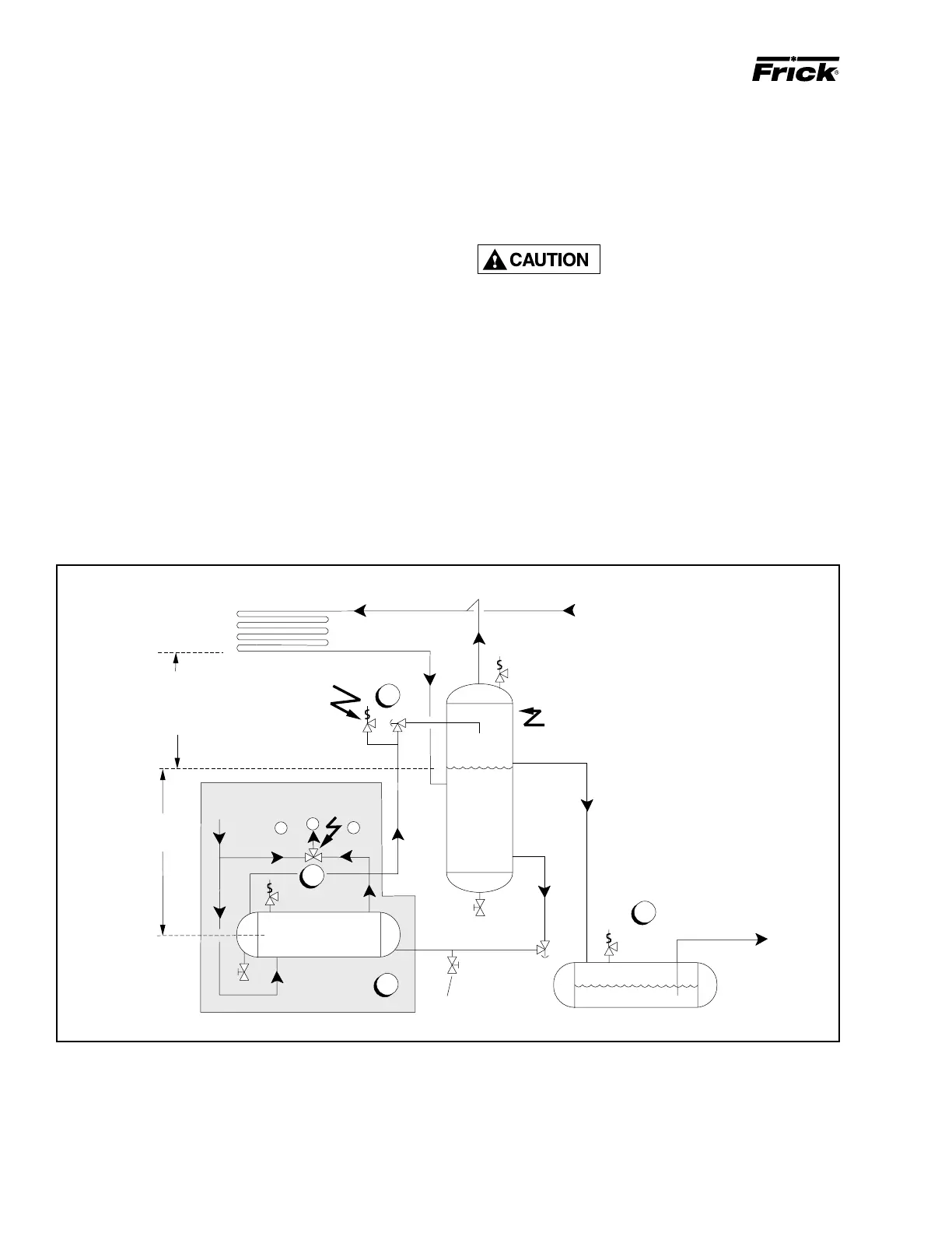
The component and piping arrangement shown in Figure
11 is intended only to illustrate the operating principles of
thermosyphon oil cooling. Other component layouts may be
better suited to a specific installation. Refer to publication
E70-900E for additional information on Thermosyphon Oil
Cooling.
Figure 11
1.
The thermosyphon oil cooler is supplied with oil side piped to the compressor unit and stub ends supplied on refrigerant side.
2. A three-way oil temperature control valve is required where condensing temperature is expected to go below 65°F.
3. A refrigerant-side safety valve is required in this location only when refrigerant isolation valves are installed between the cooler and
thermosyphon receiver. If no valves are used between the cooler and TSOC receiver, the safety valve on the TSOC receiver must be
sized to handle the volume of both vessels. Then, the safety valve on the cooler vent (liquid refrigerant side) can be eliminated.
4. The system receiver must be below the thermosyphon receiver in this arrangement.
B
C
A
OIL TEMP
CONTROL VALVE
HO
T
COOL
OIL OU
T
HOT OIL IN
THERMOSYPHON
OIL COOLER
LIQUID
LEVEL
STATIC HEAD
TO OVERCOME
CONDENSER
PRESSURE DROP
8 Ft
.
Min.
SYSTEM
CONDENSER
SAFET
Y
VALV
E
VAPOR
THERMOSYPHON
RECEIVER
LIQUID OVERFLOW
DRAIN TO
RECEIVER
TO
SYSTEM
EVAPORATO
R
SYSTEM
RECEIVER
1
3
4
(Mounted below Thermosyphon
receiver level)
2
TSOCA
Refrigerant-side drain valve
required for plate-type
thermosyphon oil coolers.

 Loading...