RWB II ROTARY SCREW COMPRESSOR UNITS
INSTALLATION
S70-210 IOM
Page 5
DBZ-B HUB FACE MAXIMUM TOTAL CLAMP BOLT TORQUE
COUPLING SPACING +/- INDICATOR READING ft-lb Nm
SIZE in. mm in. mm in. mm LUB DRY LUB DRY
MOTOR MOUNTING
The following procedure is required only when the motor is
mounted at the job site.
1. Thoroughly clean the motor feet and mounting pads of
grease, burrs, and other foreign matter to ensure firm seat-
ing of the motor.
2. Attach the motor to the base using the bolts and motor-
raising blocks, if required. Bolt snugly through the base.
3. Weld the four kick bolts into place so that they are posi-
tioned to allow movement of the motor feet.
4. Now that the motor has been set, check to see that the
shafts are properly spaced for the coupling being used.
Refer to the coupling data tables on these pages for the
applicable dimension.
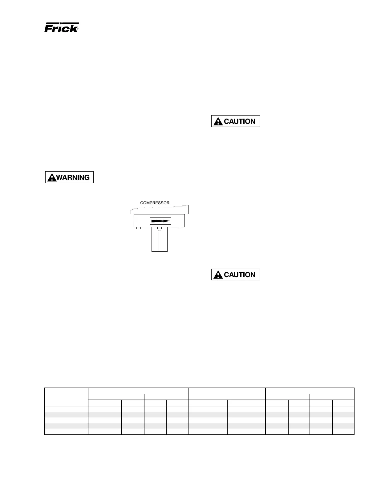
CHECKING MOTOR/COMPRESSOR ROTATION
Make sure coupling hubs are tight-
ened to the shaft before rotating the
motor to prevent them from flying
off and possibly causing serious injury or death.
COMPRESSOR ROTATION IS
CLOCKWISE WHEN FACING
THE END OF THE COMPRES-
SOR SHAFT. Under NO condi-
tions should the motor rotation be
checked with the coupling center
installed as damage to the com-
pressor may result. Bump the mo-
tor to check for correct compressor
rotation. After verification, install
gear or disk drive spacer, as applicable.
COMPRESSOR/MOTOR COUPLINGS
INSTALLATION
RWB II units are arranged for direct motor drive and require
a flexible drive coupling to connect the compressor to the
motor. Before installing, perform the following:
1. Inspect the shaft of the motor and compressor to ensure
that no nicks, grease, or foreign matter is present.
2. Inspect the bores in the coupling hubs to make sure that
they are free of burrs, dirt, and grit.
3. Check that the keys fit the hubs and shafts properly. NOTE:
Coupling keyways must be 180° opposed.
DBZ-B COUPLING – The Thomas DBZ-B coupling is used
on applications above 600 HP and with sleeve bearing mo-
tors that do not have axial end float constraint. The DBZ-B
coupling consists of two drive hubs and a flexible metal disc
drive spacer that is bolted to both hubs. A flexible steel disc
pack serves as the drive element. This disc pack is bolted to
the coupling hubs and prevents axial end float between the
compressor and motor shafts which may occur with sleeve
bearing motors. On sleeve bearing motors, the magnetic
center must be determined and maintained by securing the
coupling to the motor shaft with the shaft properly located.
Injury may occur if loose clothing,
etc. becomes entangled on the
spinning motor shaft.
If the motor is coupled to the compressor using a fixed-end-
play coupling, such as a DBZ-B coupling, and the motor is not
properly centered, additional thrust loads will be transmitted
to the compressor bearings that could result in premature
bearing failure. Install as follows:
1. Remove the eight locknuts and long bolts attaching the
center member to the disc pack.
2. Slide the disc pack and coupling hub assemblies on their
respective shafts.
3. Adjust the distance between hub faces as specified in the
DBZ-B Data Table by sliding the hubs. Key and secure hubs
to the shafts by tightening setscrews.
4. Reinstall the eight previously removed bolts and locknuts.
Alternately tighten each locknut as you would the lug nuts on
an automobile. NOTE: ALWAYS TURN THE NUT. NEVER
TURN THE BOLT.
5. Torque the locknuts to the value shown in the DBZ-B Data
Table for the size coupling being installed.
Lubricated and/or plated bolts and
locknuts develop higher bolt ten-
sion with less tightening than those
that are dry and not plated.
Torques for lubricated and/or plated bolts and locknuts will
generally fall in the lower range; while those that are dry or
as received from the factory fall into the upper range. Torque
readings should be observed while locknut is being turned.
6. Proceed to coupling alignment.
226 3-13/16 96.8 1/64 .40 .003 .076 22 43 29.8 58.3
263 4-5/16 109.5 1/32 .79 .004 .102 33 63 44.7 85.4
301 4-7/8 123.8 1/32 .79 .004 .102 50 95 67.8 128.8
351 5-7/8 149.2 1/32 .79 .004 .102 95 175 128.8 237.3
401 6-11/16 169.9 1/32 .79 .004 .102 120 200 162.7 271.2
DBZ-B COUPLING DATA TABLE

 Loading...