RWB II ROTARY SCREW COMPRESSOR UNITS
INSTALLATION
S70-210 IOM
Page 9
COMPRESSOR OIL
DO NOT MIX OILS of different
brands, manufacturers, or types.
Mixing of oils may cause exces-
sive oil foaming, nuisance oil level cutouts, oil pressure
loss, gas or oil leakage and catastrophic compressor
failure.
Use only Frick
®
refrigeration oil
and filters or warranty claims may
be denied.
The oil charge shipped with the unit is the best suited lu-
bricant for the conditions specified at the time of purchase.
If there is any doubt due to the refrigerant, operating pres-
sures, or temperatures, refer to Frick Pub. E160-802 SPC
for guidance.
INITIAL OIL CHARGE
The initial charging level is midway in the top sight glass
located midway along the oil separator shell (the sight glass
is located in the lower portion of the vertical separator).
Normal operating level is midway between the top sight
glass and bottom sight glass. The following table gives the
approximate oil charge quantity.
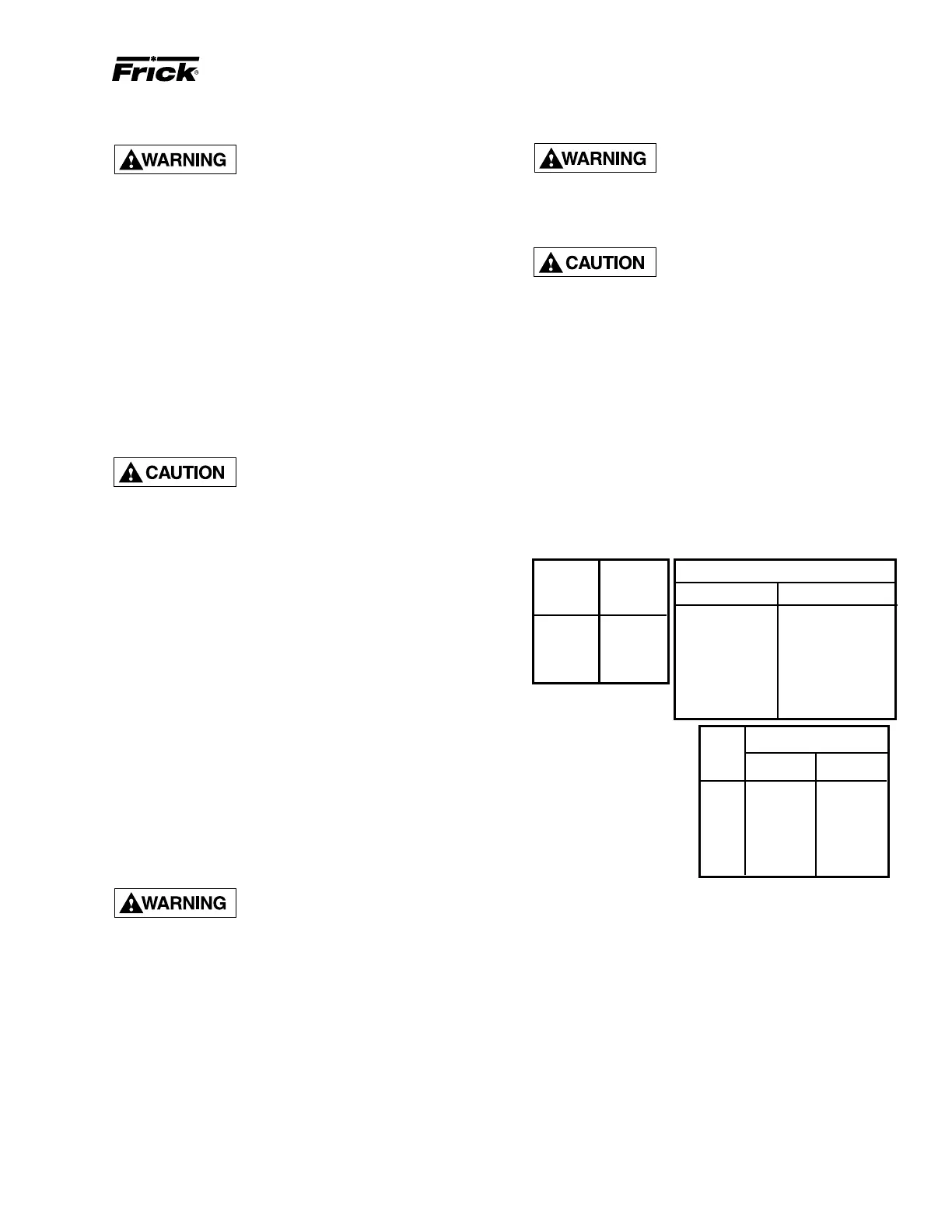
TABLE - BASIC OIL CHARGE (Gal)
* Includes total in oil sep-
arator and piping. Add
additional for oil cooler.
Add oil by attaching the end of a suitable pressure type
hose to the oil charging valve, located on the top of the oil
separator on the compressor end of the separator. Using a
pressure-type pump and the recommended Frick oil, open
the charging valve and pump oil into the separator. NOTE:
Fill slowly because oil will fill up in the separator faster
than it shows in the sight glass.
Oil distillers and similar equipment which act to trap oil must
be filled prior to unit operation to normal design outlet levels.
The same pump used to charge the unit may be used for
filling these auxiliary oil reservoirs.
NOTE: The sight glass located in the coalescing end
of the separator near the discharge connection should
remain empty.
496 (1)
676 (1)
856 (1)
1080 (1)
HOT ALIGNMENT OF COMPRESSOR/MOTOR
Hot alignments can only be made
after the unit has operated for sev-
eral hours and all components are
at operating temperatures.
Shut down the unit (proper lockout/tagout procedures
should be followed) and QUICKLY affix dial indicator to
coupling motor hub, then take readings of both the face and
rim of the compressor hub. If these readings are within toler-
ance, record reading, attach coupling guard and restart unit.
However, if the reading is not within limits, compare the hot
reading with the cold alignment and adjust for this difference;
i.e. if the rim at 0° and 180° readings indicates that the motor
rises .005" between its hot and cold state, .005" of shims
should be removed from under the motor.
After the initial hot alignment adjustment is made, restart unit
and bring to operating temperature. Shut down and recheck
hot alignment. Repeat procedure unit hot alignment is within
specified tolerance.
INSTALL COUPLING GUARD BE-
FORE OPERATING COMPRES-
SOR.
OIL PUMP COUPLING
Compressor units with prelube and direct motor/pump cou-
pled pumps need no pump/motor coupling alignment since
this is maintained by the close-coupled arrangement.
Some units utilize full and cycling lube pumps which have the
motor separate from the pump. These must be checked for
alignment due to possible misalignment which may be caused
by shipping and handling. Adjustments for that maximum mis-
alignment is less than 0.010" Total Indicator Runout (T.I.R.).
Failure to align the coupling may cause serious damage to the
pump, shaft seal, coupling, and motor bearings. Use the same
procedure as compressor/motor coupling alignment.
HOLDING CHARGE AND STORAGE
Each RWB II compressor unit is pressure and leak tested at
the Frick factory and then thoroughly evacuated and charged
with dry nitrogen to ensure the integrity of the unit during
shipping and short term storage prior to installation.
NOTE: Care must be taken when entering the unit to
ensure that the nitrogen charge is safely released.
Holding charge shipping gauges
on separator and external oil cooler
are rated for 30 PSIG and are for
checking the shipping charge only. They must be re-
moved before pressure testing the system and before
charging the system with refrigerant. Failure to remove
these gauges may result in catastrophic failure of the
gauge and uncontrolled release of refrigerant resulting
in serious injury or death.
All units must be kept in a clean, dry location to prevent
corrosion damage. Reasonable consideration must be
given to proper care for the solid-state components of the
microprocessor.
Unit which will be stored for more than two months must have
the nitrogen charge checked periodically.
BASIC*
CHARGE
(gal.)
RWB II
PLUS
MODEL
ADDITIONAL FOR OIL COOLER
REQ'D. (gal.)SIZE (in.)
6 X 60 6
8 X 60 10
6 X 120 12
8 X 120 20
10 X 120 28
12 X 120 39
16 X 120 45
1. Oil Basic Oil Charge
Sep.
Dia. Vertical Horiz.
42" 165 gal. 245 gal.
48" 220 gal. 330 gal.
54" 275 gal. –
60" 385 gal. –
66" 385 gal. –
72" 385 gal. –

 Loading...