VYPER
™
VARIABLE SPEED DRIVE
INSTALLATION
100-200 IOM (FEB 09)
Page 23
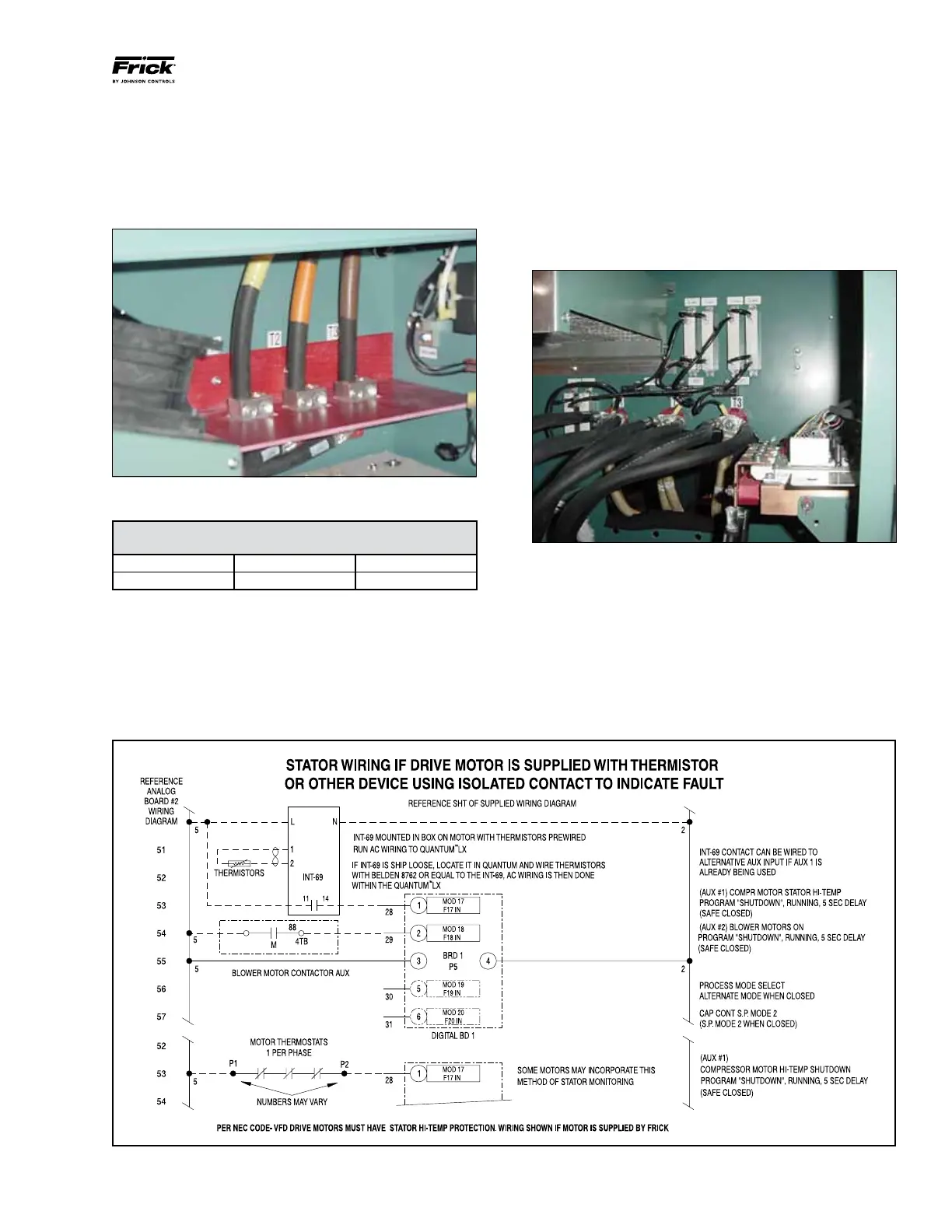
Figure 16
cutout on the back wall of the Vyper
™
cabinet (See Figure 15).
Output power connections should be tightened as shown in
the table. An appropriate conduit must be connected to the
back cutout flange of the cabinet for proper installation. These
connections are made in the factory and will be pretested
before shipment. Generally, an additional dV/dt “snubber”
filter is not required for package-mounted units.
Figure 14 - Power out connection point
Output Power Lead Torque Requirement
(Package-Mounted Vyper
™
)
Connector Size Termination Torque
3/8” lug Compression 216-240 in-lb
ELECTRICAL CONDUITS
• Allpower wiring must be contained in metallic conduit.
• Allcompressormotorwiringmustbeinaseparatemetallic
conduit.
• Oil pump motor wiring must be in a separate metallic
conduit.
• Compressormotorcoolingfanpowermustbeinaseparate
metallic conduit.
• ControlwiringbetweentheQuantum
™
LX panel and the
Vyper
™
must be contained in separate metallic conduit.
• Analog wiring needs to be in separate metallic conduit.
Figure 15 - Back wall power connections
WIRING DIAGRAM OPTIONS
The National Electrical Code requires thermal protection for
motors operating with variable-speed drive systems. Frick
employs two types of thermal protection for motors. One
method uses thermistors, and one method uses RTDs. Fig-
ures 16 - 21 show the wiring scheme for both options.
MOTOR THERMISTOR PROTECTION