VYPER
™
VARIABLE SPEED DRIVE
OPERATION
100-200 IOM (FEB 09)
Page 38
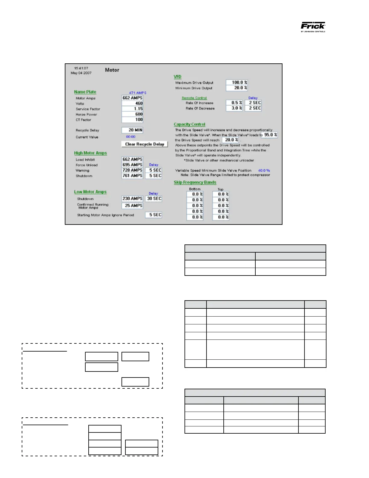
SETTING THE MOTOR SCREEN
Press: [Setpoints→Motor]
Figure 44 - Motor Screen
Nameplate
These fields should be populated with the motor nameplate
information. This is for reference only.
Recycle Delay
Use the Quantum
™
LX control panel to enter a value between
0 and 80 minutes. This represents the amount of time the
Vyper
™
will remain in standby mode before initiating a shut-
down command.
Low Motor Amps
These values are generally set as shown below. The values
may be altered in accordance with individual job require-
ments.
Low Motor Amps
Delay
Shutdown 25 AMPS 30 SEC
Confirmed Running
Motor Amps
25 AMPS
Starting Motor Amps Ignore Period 5 SEC
High Motor Amps
The High Motor Amps section is critical for protecting the
motor and the drive from high currents .
High Motor Amps
Load Inhibit
Force Unload Delay
Warning 5 SEC
Shutdown 5 SEC
“Applied Motor FLA” Calculation
IF USE
Mtr Nameplate SF=1.0 Mtr Nameplate FLA / 1.15
Mtr Nameplate SF=1.15 Mtr Nameplate FLA
There are several safety scenarios regarding the Vyper
™
and
the motor combination. To determine which strategy is appli-
cable, please follow the calculations in the following table.
Line Parameter Value
1 Applied Motor FLA
2 Applied Service Factor 1.15
3 Multiply (Line 1 x Line 2)
4 HP rating of Vyper Drive
5 Vyper Amp Limit
If Line 4 is 305/254 HP, value is 380 A
If Line 4 is 437/362 HP, value is 565 A
6 Multiply Line 5 x 1.05
• IfvalueofLine3islessthanvalueofLine6,useTableA.
• IfvalueofLine3isgreaterthanvalueofLine6,useTableB.
Table A
Parameter Equation Value
Load Inhibit =Applied Motor FLA x 1.1
Force Unload =Applied Motor FLA x 1.12
Warning =Applied Motor FLA x 1.13
Shutdown =Applied Motor FLA x 1.15