VYPER
™
VARIABLE SPEED DRIVE
MAINTENANCE
100-200 IOM (FEB 09)
Page 48
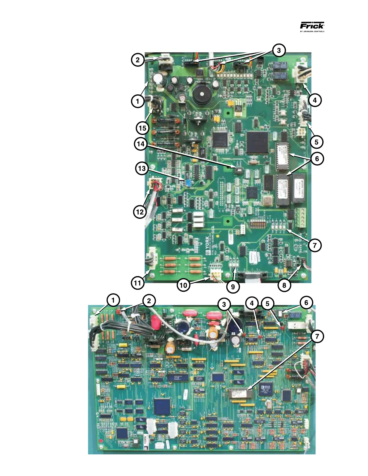
1. J5 Connector (volt-
age input / test points
2. J8 Communications
to the logic board
(J15)
3. Power Supply “OK”
LED
4. Filter “Over-Temp”
LED
5. Run LED
6. Filter ON/OFF switch
7. E-prom
1. DC Voltage Test Points
2. 24VAC Input
3. Gate Drive Connections J8, J9 & J10
4. J12 Start Input / Run Output
5. J6 to J4 of the SCR Trigger Board
6. E-prom Chips
7. Communication Indicators RX/TX, Logic
Board to Quantum LX
8. J16 Communications Cable, Logic
Board to Quantum LX
9. Communications Indicators RX/TX,
Logic Board to Filter Board
10. J15 Communications Cable, Logic
Board to Filter Board.
11. DC Bus Voltage Input
12. J2 Remove to manually engage circula-
tion pumps and internal fans
13. JOB FLA Potentiometer
14. Frequency Switch (60/50Hz)
15. Output Current input, Phase - A, B & C
The callouts on Figures 56 and 57 point
out components, indicators and test points
that can be used to aid in maintenance
amd troubleshooting of fault codes.
Figure 56 - Control Logic Board
Figure 57 - Filter Logic
Board