3.2 CONTROL PARTS
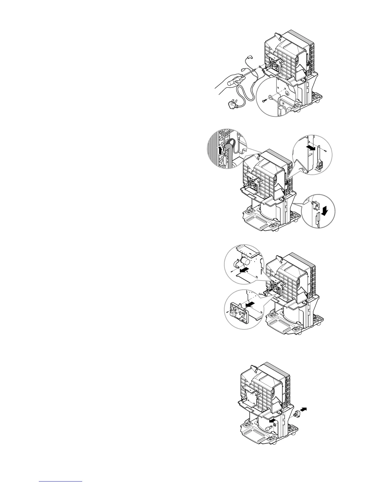
3.2.1 POWER CORD ASSEMBLY
1. After opening the control box, remove all screws
that fasten the earth wires. (See Figure 13)
2. Disconnect all leads of power cord from PWB(PCB)
ASSEMBLY, MAIN, then remove it from the control
box.
3.2.2 SENSOR ASSEMBLY
1. Disconnect sensor assembly from PWB(PCB)
ASSEMBLY, MAIN.
2. Remove a screw which fasten the humidity sensor.
(See Figure 14)
3. Remove the thermistor from holder sensor. (See
Figure 14)
4. Disconnect housing from micro switch assembly.
(See Figure 14)
3.2.3 PWB(PCB) ASSEMBLY, MAIN
1.
Disconnect all leads of the motor and the compressor
from PWB(PCB) ASSEMBLY, MAIN.
2. Remove a screw which fastens the PWB(PCB)
ASSEMBLY, MAIN and pull it out after unhooking
from 2 rectangular holes of control box (lower).
(See Figure 15)
3.2.4 CAPACITOR
(Except D30A)
1. Remove a screw that fastens capacitor.
(See Figure 15)
2. Disconnect all leads of capacitor then remove it
from control box.
3.2.5 MICRO SWITCH ASSEMBLY
1. Turn the nut counterclockwise and pull out the
micro switch from the drain pan. (See Figure 16)
—11—
Figure 15
Figure 14
Figure 16
Figure 13
 Loading...