—12—
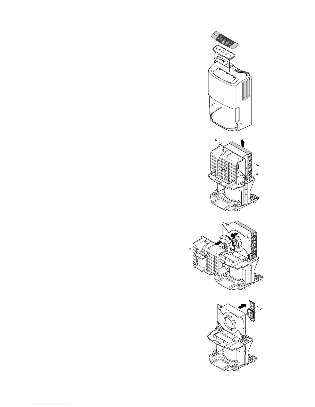
3.2.6 CONTROL PANEL
1. Disconnect housing of PWB(PCB) ASSEMBLY,
DISPLAY from PWB(PCB) ASSEMBLY, MAIN
(3.1.3).
2. Remove 5 screws that secure the PWB(PCB)
ASSEMBLY, DISPLAY to cover display.
3.2.7 HOUSING ASSEMBLY, FAN AND
MOTOR
1. Remove 4 screws that fasten the housing assembly
to heat exchanger and drain pan, and lift housing
assembly upward after unhooking 2 hooks on the
housing. (See Figure 18)
2. Remove a screw that secures housing and orifice,
and separate the orifice from housing after
unhooking 3 hooks on the housing. (See Figure 19)
3. Turn the nut clockwise and full out the fan by hands
carefully. (See Figure 19)
4. Unfasten 2 screws that secure the motor.
(See Figure 20)
5. Separate the motor.
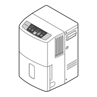
Figure 17
Figure 18
Figure 19
Figure 20
 Loading...