16
C. INSTALLATION OF THE UNIT
C.4 Window Installation (Continued)
WARNING
Falling Object Hazard
Not following Installation Instructions
for mounting your air conditioner can
result in property damage, injury, or
death.
CAUTION
Cut/Sever
Although great care has been
taken to minimize sharp edges
in the construction of your unit,
use gloves or other hand
protection when handling unit
Failure to do so can result in minor
to moderate personal injury.
STEP 10. INSTALL THE R1 INSULATION PANEL – To minimize air leaks and
ensure optimal insulation, install the included R1 insulation panel (14
in parts list) (see Figure C.4.14).
First, measure the width from one side of the cabinet/ sleeve (covering
the side angles where the wingboard was just secured) to the end of the
wingboard (see Figure C.4.14.1).
Next, cut the R1 insulation panel to the measured width and remove
protective cover, exposing adhesive on back panel (see Figure
C.4.14.2).
Last, evenly apply the adhesive side of the panel across the entire
height and width from side angle to wingboard panel (see Figure
C.4.14.3).
Repeat the steps above for the other wingboard panel.
STEP 11. INSTALL THE WINDOW SEALING GASKETS – Measure and cut
the dark foam window seal gasket (Item 12) and install it between
the upper glass panel and the top part of the window sash (see
Figure C.4.14.1).
STEP 12. Carefully team lift the chassis and set it into the cabinet. Slide the
chassis stopping approximately 3″ from full insertion. Insert the
chassis seal gasket (Item 13) one inch deep between the chassis and
the cabinet (see Figure C.4.15). A paint stir stick or ruler might be
helpful here. Begin inserting the gasket at either bottom corner and go
up the side, across the top, and down the opposite side. Then push
the chassis all the way into the cabinet.
NOTE: If the chassis seal gasket is not installed or installed improperly, the
operation of the unit will be negatively affected. Operational noise and
outside noise will also be amplied.
STEP 13. Reattach the EntryGard
™
chassis and EntryGard
™
retainer wire with
the same screw retained in Step 1 (see Figure C.4.1).
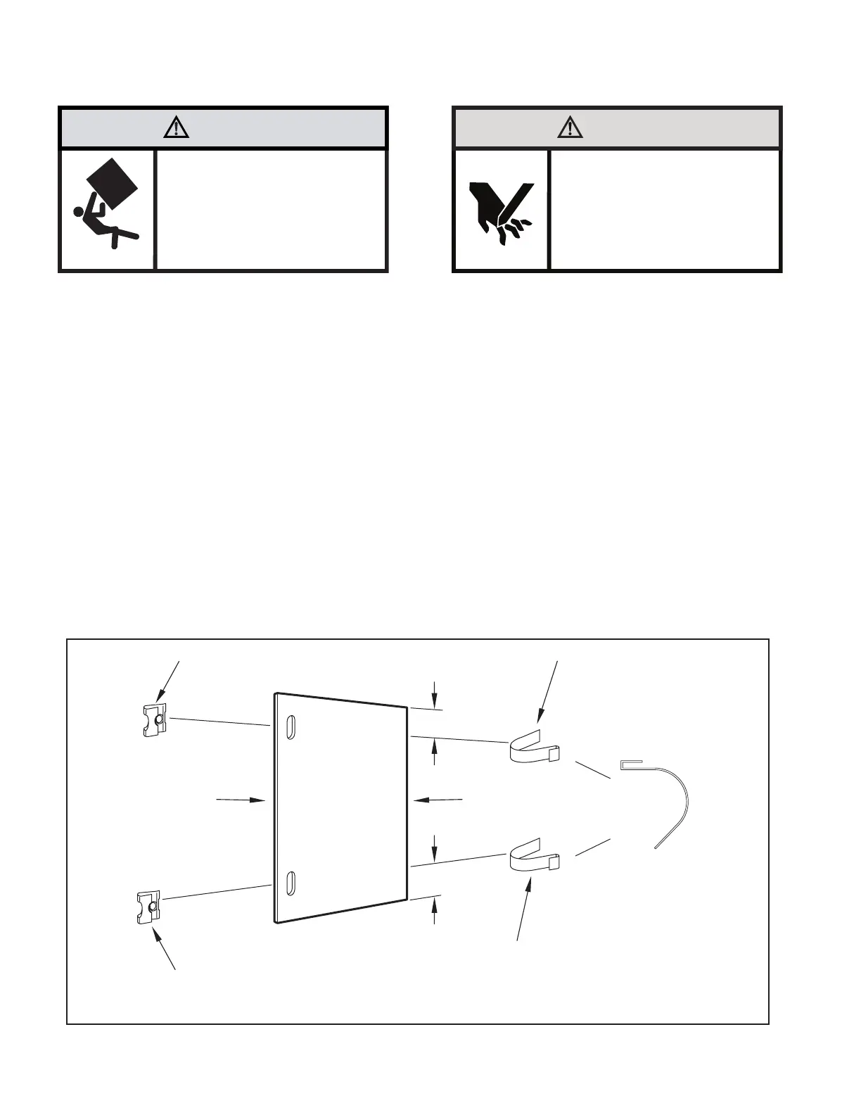
Figure C.4.12
“J” TYPE SPEED NUT
(ITEM #9) 2 REQUIRED
SPRING STEEL CLIP
(ITEM 10) 2 REQUIRED
ROTATED 90°
CUT EDGE
CUT
WINGBOARD
PANEL
CENTER THE HOLE IN THE
SPEED NUT OVER THE SLOT
IN THE WINGBOARD PANEL
SLIDE CLIP OVER CUT EDGE
OF WINGBOARD PANEL
3″
3″