24
C. INSTALLATION OF THE UNIT
C.5 Thru-the Wall Installation (Cont.)
FRR031
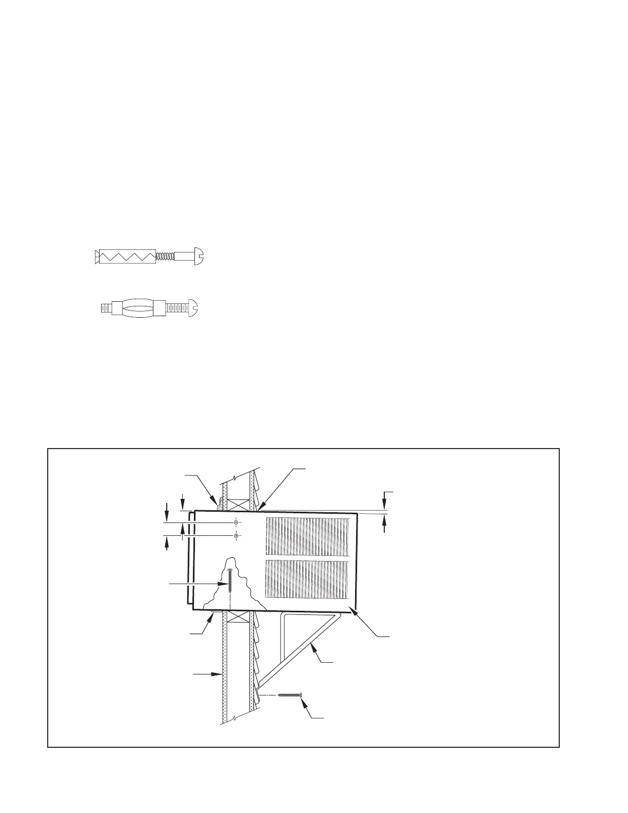
TRIM MOULDING
SILL PLATE GUIDE CHANNEL
NOTE: SUPPORT BRACKET MAY BE OMITTED
FROM THRU-THE-WALL INSTALLATIONS IF
THE CABINET IS SECURED AS FOLLOWS:
DRILL TWO HOLES IN EACH SIDE AND
INSTALL 4 FASTENERS (2 EACH SIDE).
USE #12 x 2″ SCREWS, (ITEM 4).
TOGGLE BOLTS OR EXPANSION BOLTS
MAY BE REQUIRED.
CAULK ALL SIDES WEATHER TIGHT
INSIDE AND OUTSIDE
SCREW #12 x 2″
LONG (USE 3)
(ITEM 4)
3″
4″
INSIDE WALL SURFACE
3
/8″ SLOPE DOWN
CABINET
SUPPORT BRACKETS
SCREW #12 x 2″ LONG
DRILL
5
/32″ DIA. PILOT HOLES.
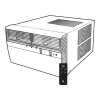
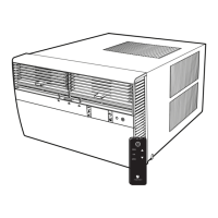
STEP 8. Slide the cabinet into the hole far enough to allow the guide-channel
of the sill plate to contact the inside wall surface (Figure C.5.9).
STEP 9. Drill three (3)
5
/32″ diameter pilot holes (use the sill plate holes as a
guide) into the frame and install three (3) #12 x 2″ long screws (Item 4)
(Figure C.5.9).
NOTE: Alternate fasteners are required when securing the sill plate or support
brackets to material other than wood (cinder block, brick, masonry, or
concrete). These items can be purchased at your local hardware store.
NOTE: DO NOT LEVEL the cabinet from front to back. Make sure there
is approximately
3
/8″ to
1
/2″ slope (
1
/8 to
1
/4 bubble on the level)
toward the outside of the house.
STEP 10. Drill two (2)
5
/32″ diameter pilot holes in each cabinet side at the
locations shown (Figure 83) and install four (4) #12 x 2″ screws (Item
4). Provided that Step 5 (hole construction) provides a sturdy
mount with solid vertical studs, support brackets may not be required.
The installation must support the weight of the unit plus an additional
weight of 400 pounds on the rear of the cabinet. If support brackets
(Item 1) are available, they can be installed as shown in Figure C.5.9
STEP 11. Carefully team lift the chassis and set it into the cabinet. Slide the
chassis stopping approximately 3″ from full insertion. Insert the chassis
seal gasket (Item 13) one inch deep between the chassis and the
cabinet (see Figure C.5.10). A paint stir stick or ruler might be helpful
here. Begin inserting the gasket at either bottom corner and go up
the side, across the top, and down the opposite side. Then push the
chassis all the way into the cabinet.
NOTE: If the chassis seal gasket is not installed or installed improperly, the
operation of the unit will be negatively affected. Operational noise and
outside noise will also amplied.
STEP 12. Reattach the EntryGard
™
chassis and EntryGard
™
retainer wire with the
same screw retained in Step 1 (see Figure C.5.1)..
EXPANSION ANCHOR BOLT
MOLLY OR TOGGLE BOLT
Figure C.5.9