EasyManua.ls Logo

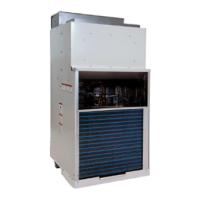
Friedrich VERT-I-PAK VHA09K34RTQ User Manual

Friedrich VERT-I-PAK VHA09K34RTQ
72 pages
To Next Page IconTo Next Page
Page #1 background imageLoading...
Page #1 background image
Service Manual
95992013_00
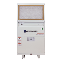
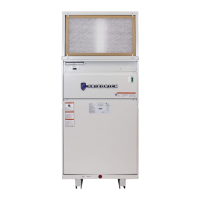
Single Package Vertical Heat Pump System
R-410A Refrigerant
THE EXPERTS IN ROOM AIR CONDITIONING
VHA - 18K25RTQ, 18K34RTQ, 18K50RTQ, 18K75RTQ
VHA - 18R25RTQ, 18R34RTQ, 18R50RTQ, 18R75RTQ
18K
24K
VHA - 24K25RTQ, 24K34RTQ, 24K50RTQ, 24K75RTQ, 24K10RTQ
VHA - 24R25RTQ, 24R34RTQ, 24R50RTQ, 24R75RTQ, 24R10RTQ
VHA - 09K25RTQ, 09K34RTQ, 09K50RTQ
VHA - 09R25RTQ, 09R34RTQ, 09R50RTQ
9K
12K
VHA - 12K25RTQ, 12K34RTQ, 12K50RTQ
VHA - 12R25RTQ, 12R34RTQ, 12R50RTQ

Table of Contents

Questions and Answers:

Friedrich VERT-I-PAK VHA09K34RTQ Specifications

General IconGeneral
Cooling Capacity (BTU/hr)9, 000
Heating Capacity (BTU/hr)9, 000
HSPF9.0
Voltage208/230
Phase1
Frequency60
RefrigerantR-410A
Airflow (CFM)300
Sound Level (dB)52

Summary

INTRODUCTION

General Safety Information

Important safety messages and hazard alert symbols used in the manual.

Hazard Categories

Details on electrical, mechanical, and refrigeration hazards.

SPECIFICATIONS

Electrical Requirements and Safety

Guidelines for fuse, circuit breaker, grounding, and wire sizing.

OPERATION

Unit Sequence of Operation

Step-by-step description of unit power-up and operation modes.

Pressure Switch Operation

Details on low and high pressure switch functions in cooling/heating.

Defrost Mode Operations

Details on defrost mode, calibration, activation, and control.

REMOVE AND INSTALL THE CHASSIS

Chassis Removal and Installation

Procedures for removing and installing the unit chassis.

EXTERNAL STATIC PRESSURE

Checking External Static Pressure

Steps to measure and determine external static pressure.

TROUBLESHOOTING

Control Diagnostic Modes

Explains LED codes and diagnostic descriptions for troubleshooting.

COMPONENT IDENTIFICATION

Electrical Control Box Components

Images and labels for components in the electrical control box.

Defrost Control Board Identification

Images and labels for the defrost control board.

COMPONENT TESTING

Reversing Valve Testing and Operation

Explains reversing valve function, testing, and touch chart.

Compressor Testing and Checks

Procedures for compressor voltage, amperage, resistance, and efficiency.

Blower Motor and Outdoor Fan Service

Diagnosis and replacement for blower motor and outdoor fan.

R-410A SEALED SYSTEM REPAIR

WIRING DIAGRAMS

APPENDIX

Related product manuals