TTJ-0198 (10/97) (Page 16 of 64)
COMPONENTS OPERATION & TESTING
WARNING
DISCONNECT ELECTRICAL POWER TO
UNIT BEFORE SERVICING OR TESTING
COMPRESSORS
Compressors are single phase, 115 or 230/208 volt, de-
pending on the model unit. All compressor motors are
permanent split capacitor type using only a running ca-
pacitor across the start and run terminal.
All compressors are internally spring mounted and ex-
ternally mounted on rubber isolators.
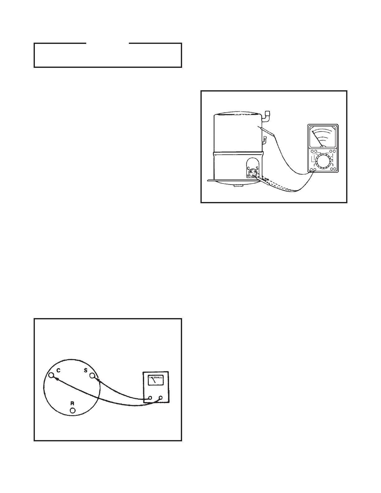
COMPRESSOR WINDING TEST (See Figure 1)
Remove compressor terminal box cover and disconnect
wires from terminals. Using an ohmmeter, check conti-
nuity across the following:
1. Terminal “C” and “S” - no continuity - open wind-
ing - replace compressor.
2. Terminal “C” and “R” - no continuity - open wind-
ing - replace compressor.
3. Terminal “R” and “S” - no continuity - open wind-
ing - replace compressor.
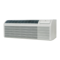
GROUND TEST
Use an ohmmeter set on its highest scale. Touch one
lead to the compressor body (clean point of contact as
a good connection is a must) and the other probe in
turn to each compressor terminal (see Figure 2.) If a
reading is obtained, the compressor is grounded and
must be replaced.
Figure 2: Typical Ground Test
CHECKING COMPRESSOR EFFICIENCY
The reason for compressor inefficiency is normally due
to broken or damaged suction and/or discharge valves,
reducing the ability of the compressor to pump refriger-
ant gas.
This condition can be checked as follows:
1. Install a piercing valve on the suction and dis-
charge or liquid process tube.
2. Attach gauges to the high and low sides of the
system.
3. Start the system and run a “cooling or heating
performance test.”
If test shows:
A. Below normal high side pressure.
B. Above normal low side pressure.
C. Low temperature difference across coil.
The compressor valves are faulty - replace the
compressor.
THERMAL OVERLOAD (External)
Some compressors are equipped with an external over-
load which is located in the compressor terminal box
adjacent to the compressor body (see Figure 3.)
Figure 1: Compressor Winding Test
 Loading...