FC-302 Data Radio User Manual
FC-302 is comprised of three PCBs (an Mainboard PCB, a Power board and a Modem PCB). These
boards are an 18 pin female and male connector. The digital board is interfaced with external data equipment
through the 15 pin d-sub male connector, which controls the radio and data receiving and sending.
3.1 Power Supply
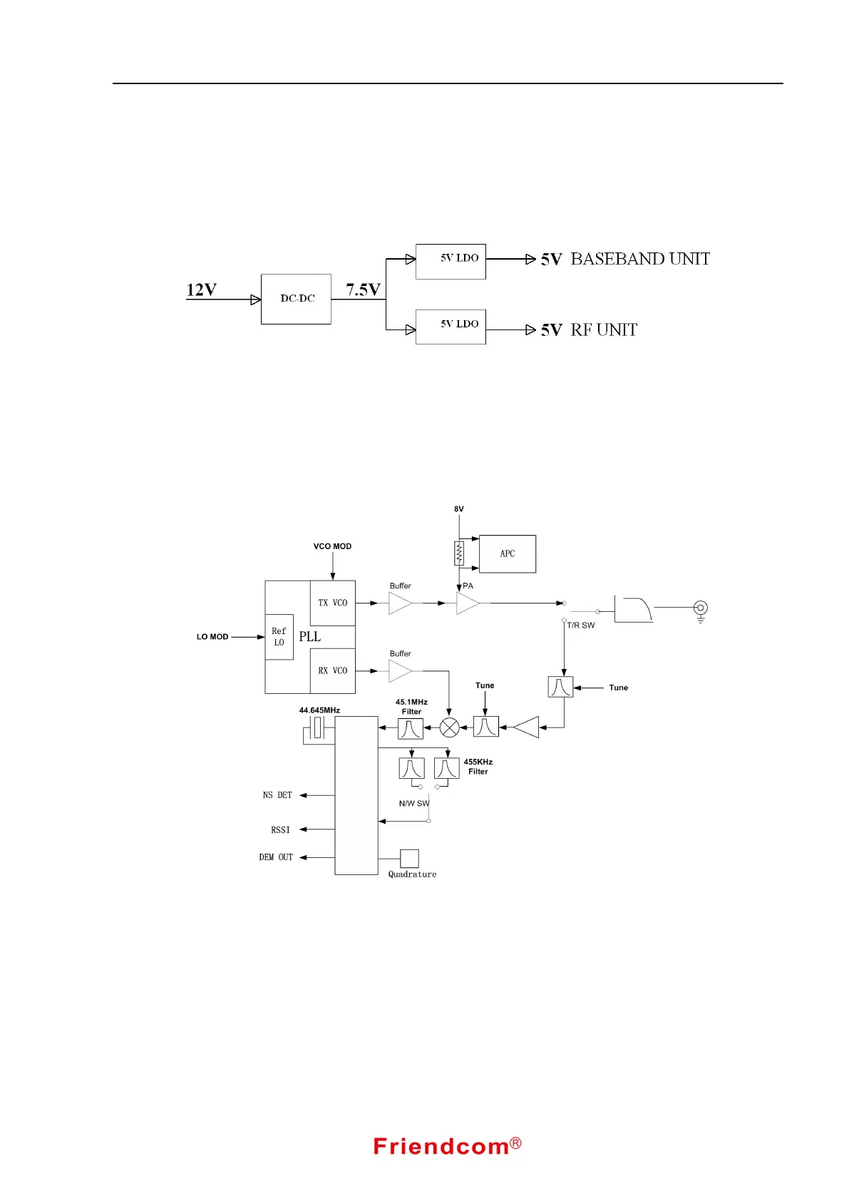
Fig. 2 Power Supply Diagram
Input 9V~12V will be lowered to 7.5V by DC-DC before it input to the machine. Then it divides into to
circuits through LDO and stabilizes at 5V. One circuit supplies power for RF unit and the other supplies power
for baseband unit. By adopting high-efficiency DC-DC to convert input voltage, the stabilities of all technical
features can be assured.
3.2 RF Channel
Fig. 3 RF Circuit Diagram
FC-302 receiver adopts two-stage intermediate frequency, 45.1MHz and 455KHz. When in RX mode,
the RF signal pass though Antenna Port, Low Pass Filter and RF switching circuit then finally sent to a
Low-noise Band-pass Amplifier Circuit for being magnified. The magnified RF signal and the first local
oscillator signal outputted by VCO will proceed mixing in the first mixer, then produce first intermediate
frequency 45.1MHz. The first intermediate frequency would be filtered by a 45.1MHz crystal band-pass filter.
After buffer amplification it is sent to Pin 16 of IF-PLL demodulation chip. Inside the IF-PLL demodulation
chip the signal will mix with the second local oscillator and produce second intermediate frequency 455KHz.
The 455KHz intermediate frequency will be selected , magnified, limited, and demodulated by the band-pass
filter and then transferred into a baseband signal.