FC-302 Data Radio User Manual
transferred to the audio power amplifier to drive trumpet for voice. Then users can hear his own voice when
sending the voice.
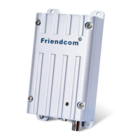
3.6 CTCSS/DCS
Fig.7 CTCSS/DCS Processing Block Diagram
CTCSS/DCS encoding and decoding is completed by the MCU. When radio is in TX mode, subaudio sent
from the MCU is directly transferred to the carrier modulator-carrier modulation via second-order RC filter.
When the radio in Rx mode, baseband signal output form intermediate-frequency demodulator chip process the
audio filtering after the DC level shift and switching between wideband and narrowband. The audio filter is an
300Hz low pass filter and select sub audio signal sent to the MCU for decoding.
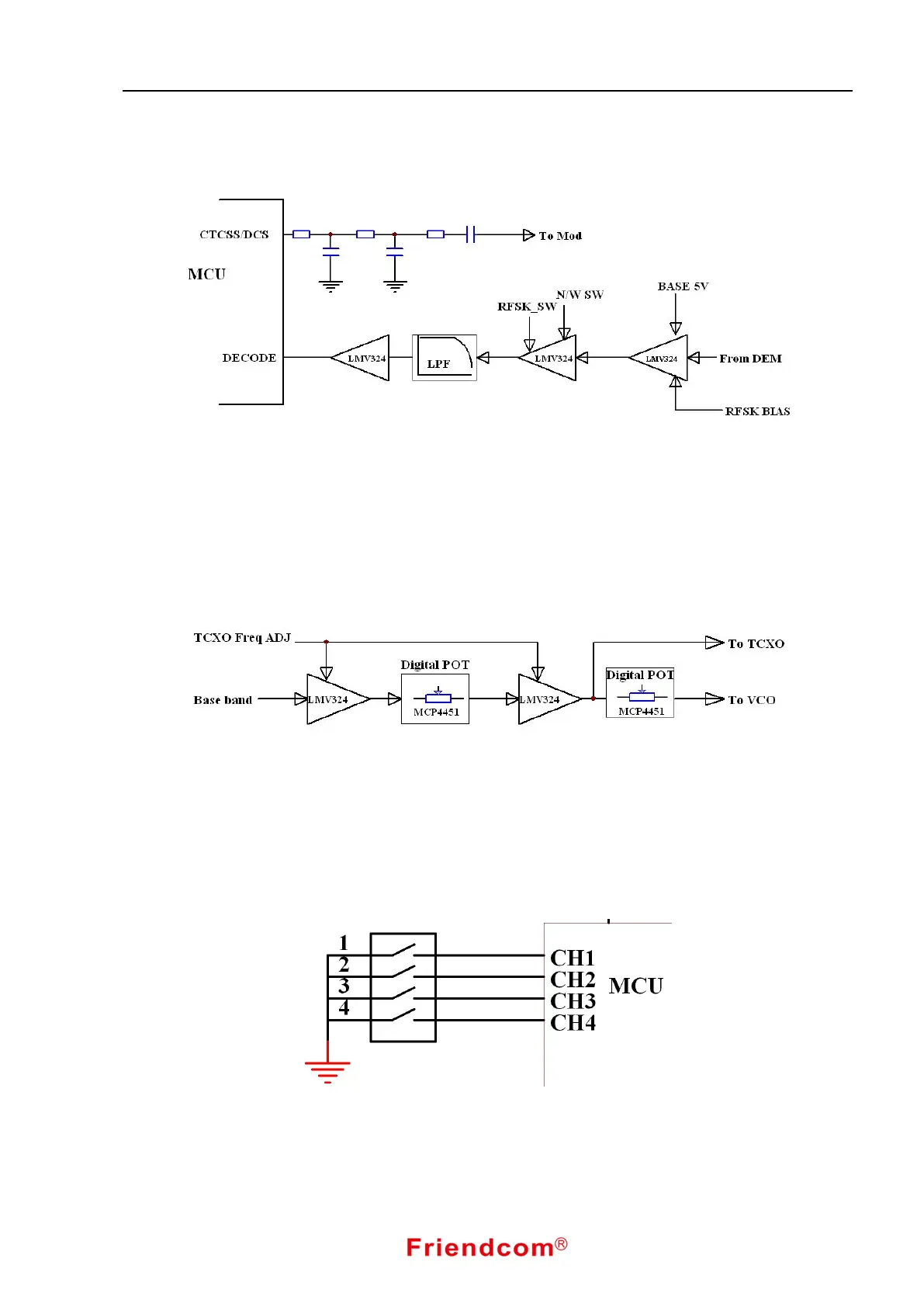
3.7 Two-Point Balanced Modulation
Fig.8 Two-point Balanced Modulation Diagram
Two-point balanced modulation is used when carrier is modulated by baseband signal. That is one signal
modulate reference frequency source of the frequency synthesizer, another signal modulate the VCO frequency.
Two-point modulation have characteristics of linearity and bandwidth etc. The radio two-point modulation uses
DC coupling mode, making modulation signal low end frequency response smoother.
3.8 Channel Selection Circuit
Fig.9 Channel Selection Diagram
The radio’s 16 channels can be select by inner dip switch (4 bits). MCU reads the status of the switch to
select wanted channel by changing dip switch(4 bits). Besides hardware control, software control is also
available when banning dip switch.