FC-302 Data Radio User Manual
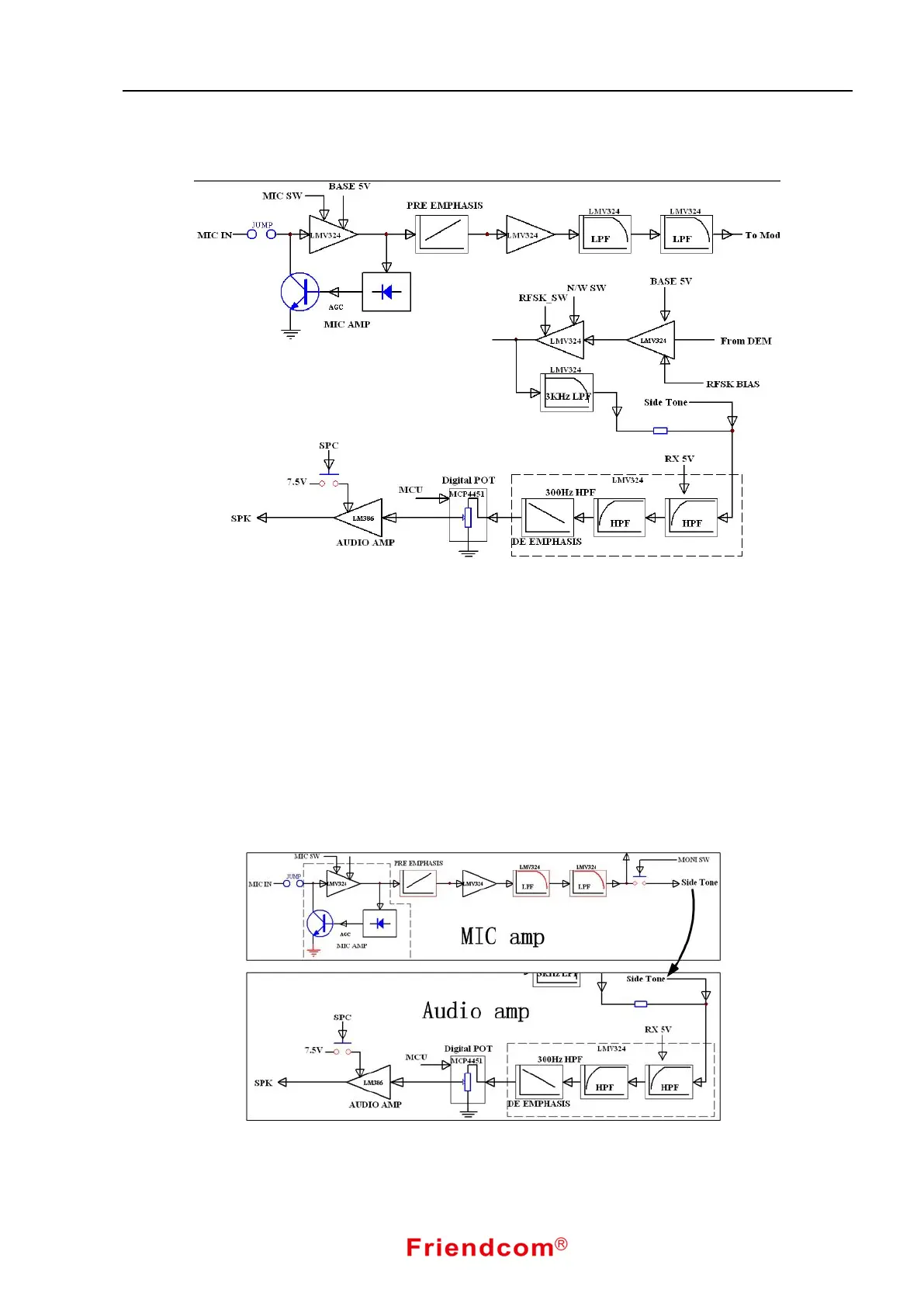
3.4 Voice Processing Circuit
Fig.5 Voice Processing Block Diagram
When in TX mode, speech signal is transferred from the MIC IN to amplifier with automatic gain control
function for amplification , and then is sent to the modulator through the audio frequency pre- emphasis circuit,
a limiter circuit and low pass filter.
When in RX mode, the intermediate frequency demodulation chip output baseband signal. The baseband
signal is amplified and go through DC level shift, narrowband and wideband switching. the filter is consist of
3KHz low-pass filter and 300Hz high-pass filter, mainly used for tone and high-frequency noise filtering to
improve signal to noise ratio(SNR). Then the audio signal is output from the SPK after volume controls and
power amplifier.
3.5 Side Tone Circuit
Fig. 6 Sidetone Block Diagram
When sidetone function is enable, signal amplified by MCU will be separated. One part of signal will be