3
INSTALLATION INSTRUCTIONS - FREESTANDING GAS RANGE
5.6 CAPACITY
Fig. a
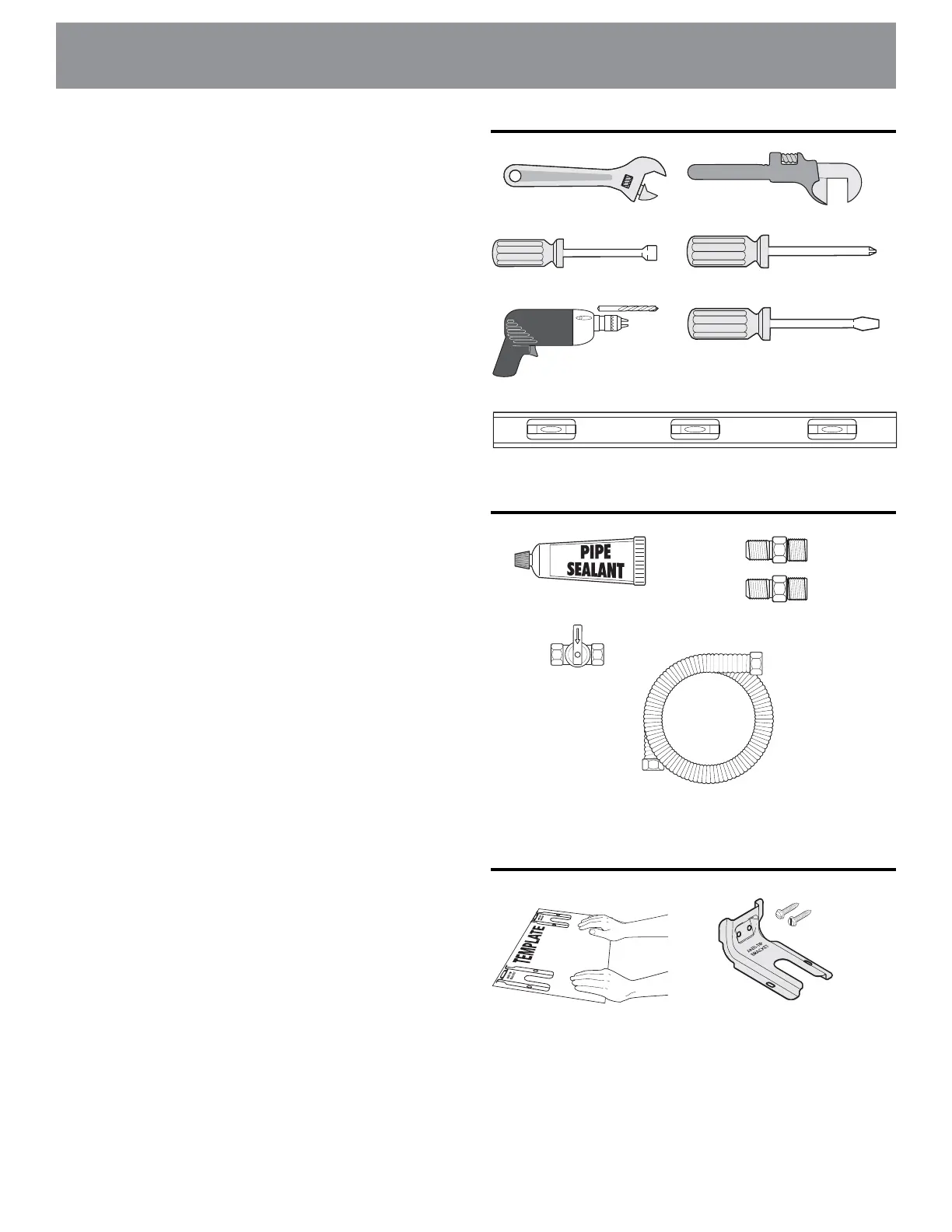
Toolsyouwillneed
(Wear safety glasses when using tools):
For leveling legs and Anti-Tip Bracket:
• Adjustablewrenchorchannellockpliers(Fig.a)
• 5/16”Nutdriveroratheadscrewdriver(Fig.b)
• Electricdrill&1/8”drillbit(3/16”Masonrydrillbitif
installinginconcrete)(Fig.c)
• Level(Fig.d)
For gas supply connection:
• Adjustablewrenchandpipewrench(Figs.a&e)
Forburnerameadjustment:
• Phillipsheadandsmallat-bladescrewdrivers(Figs.f
&g)
Materialsyouwillneed:
• PipejointsealantthatresistsactionofLP/Propanegas
(Fig.h)
• Gaslinemanualshut-offvalve(Fig.i)
• Anewexiblemetalapplianceconduit(1/2”NPTx
3/4”or1/2”I.D.)mustbedesigncertiedbyCSA
International.Becausesolidpiperestrictsmovingthe
range,werecommendusinganewexibleconduit
(4to5footlength)foreachnewinstallationand
additionalreinstallations.(Fig.j)
• Usenewareunionadapters(1/2”NPTx3/4”or1/2”
I.D.)(Fig.k)
Materialssuppliedwithappliance:
• Anti-TipTemplate(Fig.l)
• Anti-Tipbracket;includes2mountingscrews(Fig.m)
Tools
Fig. f
Materials
Fig. h
Fig. i
Fig. j
Fig. k
Fig. d
Fig. c
Fig. g
Fig. b
Fig. e
Fig. l
Fig. m
Materialssuppliedwithappliance