4
INSTALLATION INSTRUCTIONS - FREESTANDING GAS RANGE
5.6 CAPACITY
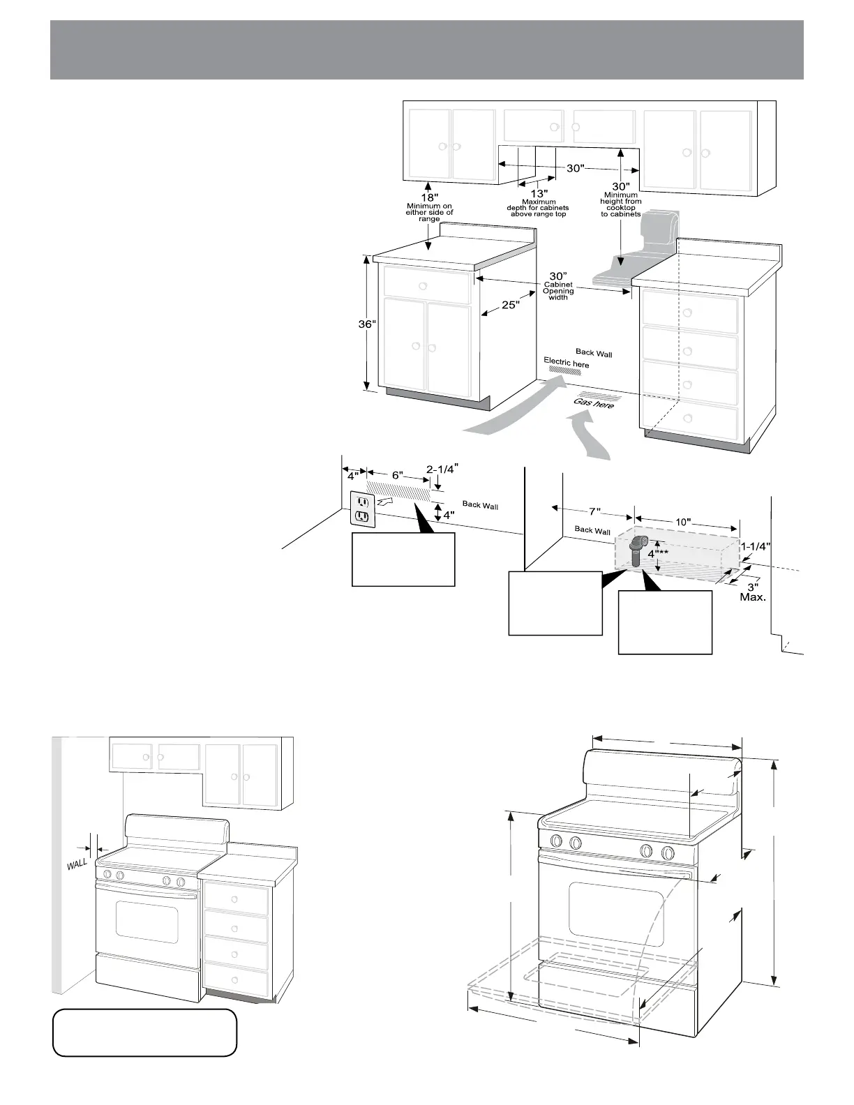
Fig. 1
This shaded floor
area is for thru the
floor connection of
gas pipe stub and
shut-off valve.
Add 1/2” NPT 90°
black pipe elbow to
the gas supply pipe
stub and orient the
elbow as shown.
Fig. B
Fig. A
Fig. C
Install a flush mount
120V electrical wall
outlet in the shaded
area.
Installation with cabinets
Check location where the range will
be installed for proper electric and gas
supply,andstabilityoftheoor.
The dimensions shown here
must be used and are minimal
unless otherwise stated. These
measurements do not allow for any
clearance below the cooking top or at
the rear of the range.
Contact surface must be solid and
level.
Things to remember:
• Donotsealtherangetoside
cabinets.
• Donotpinchthepowersupply
cord between the range and rear
wall.
• Ifcabinetdepthisgreaterthan
25”,theovenfrontframemust
extendbeyondcabinetfrontby
1/2”minimum(SeeFig.1).
• Allopeningsinthewalloroor
where the range is to be installed
must be sealed.
•Thegassupplypipestuband
elbow assembly centerline should
notexceed4”heightfromthe
oor.
Installationbesidewall
If installing beside a wall, the minimum
distance to combustible wall on either side of
rangeabove36”heightshouldbeaccording
totheBTUofthelargestburner(SeeFig2).
Fig. 2
* 9500 BTU or less 2”
10,000-16,999BTU 3”
17,000BTUorgreater 5”
*
36±1/8”
(Adjustable)
46-5/8”
max
door
open
29-7/8”
25-3/4”
48-1/2”
max
30”
29-1/4”
max
door
closed
Fig.3