EasyManuals Logo

Frigidaire MWV150KB User Manual

Frigidaire MWV150KB
72 pages
To Next Page IconTo Next Page
To Previous Page IconTo Previous Page
Page #16 background imageLoading...
Page #16 background image
INSTALLATION OVERVIEW
B1. Prepare Rear Wall
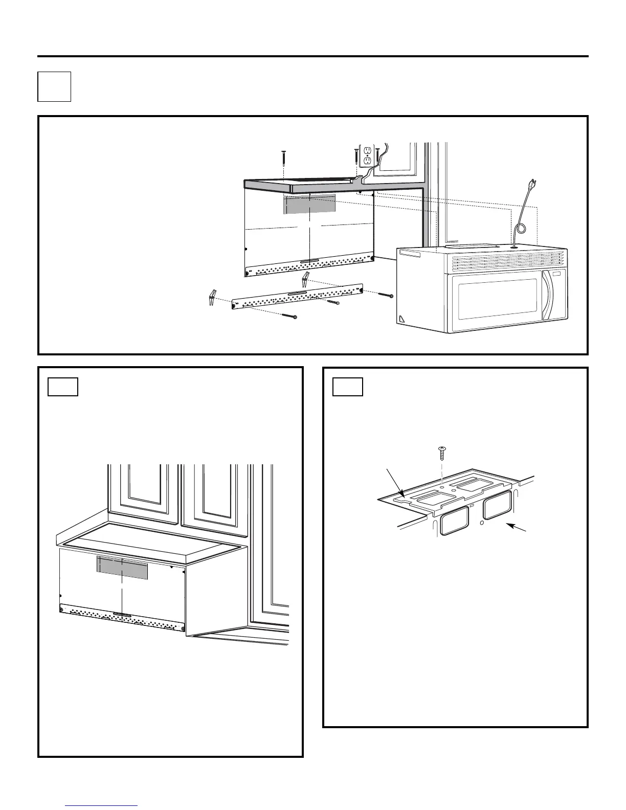
B3. Attach Mounting Plate to Wall
B4. Prepare Top Cabinet
B5. Adjust Blower
B6. Mount the Microwave Oven
IMPORTANT NOTES:
Make sure the screws for the
blower motor and blower plate
are securely tightened when
they are reinstalled. This will
help to prevent excessive
vibration.
been properly routed and secured,
and that the wires are not pinched.
Remove and save the screw that holds the blower
plate to the microwave. Lift off the blower plate.
Back of
Microwave
Installation Instructions
PREPARING THE REAR WALL
FOR OUTSIDE BACK EXHAUST
B1.
You need to cut an opening in the rear wall for
outside exhaust.
Read the instructions on the REAR
WALL TEMPLATE.
Tape it to the rear wall.
Cut the opening, following the instructions of the
REAR WALL TEMPLATE.
B2.
OUTSIDE BACK EXHAUST (Horizontal Duct)
B
Blower Plate
REMOVE BLOWER PLATE
B2. Remove Blower Plate
3
/
8" T
O E
D
GE


































NO
TE
: IT IS VE
RY IM
POR
T
AN
T
TO
RE
AD
A
ND
FOLL
OW
TH
E
DIR
EC
TIONS
IN T
HE IN
STA
L
LATIO
N
INS
TR
U
CTIO
NS
BEFO
RE
PR
OC
EED
ING
WITH
TH
I
S
RE
AR
W
ALL
TEMP
LA
TE
.
T
h
is
Re
ar
W
all
T
e
m
pl
a
t
e
s
erv
es
t
o
p
osit
i
on
t
h
e
bot
t
om
m
ount
ing
pla
t
e
a
nd
t
o
lo
c
a
t
e
t
he
h
or
i
z
o
nt
al
exhaust
ou
t
let
.
1.
Us
e
a
le
vel
t
o
check
t
hat
t
h
e
t
e
m
pla
t
e
is
posi
t
ione
d
accurat
ely.
2.
Loc
at
e
and
m
ark
a
t
l
ea
s
t
one
st
ud
on
t
he
l
ef
t
or
right
side
o
f
t
h
e
c
e
nt
er
l
ine.


I
t
is
im
port
ant
t
o
u
se
at
leas
t
on
e
woo
d
scr
e
w
m
oun
t
e
d
f
irmly
in
a
st
ud
t
o
s
up
port
t
he
wei
ght
of
t
h
e
m
i
crow
ave.
M
a
r
k
t
wo
a
ddit
ion
al
,
e
v
enly
spa
ced
loca
t
i
on
s
f
or
t
h
e
s
uppl
ied
t
og
g
le
bolt
s.
3.
Dr
i
ll
h
oles
in
t
h
e
m
ark
ed
l
oca
t
io
n
s.
Wh
ere
t
h
er
e
i
s
a st
ud,
dri
ll
a
3
/
1
6"
ho
le
f
o
r
wood
screws.
F
o
r
h
ol
es
t
hat
do
n
ot
li
ne
up
wit
h
a
st
u
d,
d
r
il
l
5
/
8
"
hole
s
f
or
t
oggle
b
olt
s
.


DO
NO
T
I
N
S
T
ALL
T
HE
M
O
UNT
I
NG
P
LAT
E
AT
T
HI
S
T
I
M
E.
4.
Rem
o
v
e
t
he
t
em
plat
e
f
rom
t
he
rear
wall.
5.
Review
t
h
e
I
nst
alla
t
io
n
I
n
s
truc
t
ion
boo
k
f
or
y
our
inst
allat
io
n
sit
u
a
t
io
n.
Lo
cate
and
mar
k hol
es to
a
lig
n w
ith ho
l
es
in the
mo
u
nti
ng p
late
.
IMP
O
RTA
NT:
LOCATE
AT LE
A
ST ON
E
STU
D
O
N
EITH
ER
S
ID
E
O
F
TH
E
C
E
NTER
LIN
E
.
M
A
R
K TH
E L
OC
AT
ION FOR
2 AD
D
IT
I
O
NAL
,
EVEN
LY
SP
ACE
D TOGG
LE BO
LTS IN
THE
MOU
NTIN
G
PLA
TE
AREA.
Lo
cate
and
mar
k hol
es to
a
lig
n w
ith h
o
les
in the
mo
unti
ng
p
late
.
IMPORTA
NT:
LO
CATE
AT LE
AST ON
E
STU
D O
N EIT
H
ER
SIDE
O
F
TH
E CE
N
TER
LIN
E.
MA
RK TH
E
L
OCAT
IO
N FOR
2 AD
DIT
I
O
NAL
, EVEN
LY
SP
AC
E
D
TOGG
LE
BO
LTS
IN
THE
M
OU
NTI
N
G PLA
TE
AR
EA.
Trim
the
r
ea
r wa
ll te
mpla
te a
l
o
n
g the d
otted
line
.
Tri
m
the
r
ea
r
wall
te
mpla
te
a
l
o
ng
the
d
otted
lin
e
.
















1
2
"
4
"
Dar
le
vu
elta
a
la
ho
ja
pa
r
a
co
n
sul
tar
la
ve
r
sión
en
E
spañ
ol.
Make sure the motor wiring has
EN-16
3
/
8
"
TO
EDGE






































NO
TE: IT IS
VERY IMP
O
RTANT
TO
READ AND FO
LLO
W THE
DI
RECTIO
NS
IN THE INST
AL
LATIO
N INST
RUCTIO
NS
BEFO
RE
PRO
CEEDING
WITH T
HIS
REAR W
ALL TEMP
LAT
E.
T
his
Rear
Wall
T
e
mplate s
er
v
es
to
po
s
iti
o
n th
e
b
otto
m
mo
un
ting
p
lat
e and
to l
oc
a
te
t
he ho
r
iz
o
n
tal
e
xha
us
t
ou
tle
t.
1. Us
e a lev
el
to
c
he
c
k
tha
t th
e t
e
mpla
te
is
p
os
it
ion
ed
a
c
cur
ately
.
2. L
o
c
ate
and
ma
r
k
at le
as
t o
ne
s
tu
d on
th
e
left or
r
igh
t s
id
e
of t
he
c
en
te
r
lin
e.


It is
im
p
or
t
an
t to us
e a
t le
a
s
t one
w
o
o
d
s
c
r
e
w mou
nted
fi
r
mly
in
a
s
tud
to s
u
pp
o
rt th
e
we
igh
t
of th
e m
ic
r
owav
e
. Mar
k
two ad
diti
on
a
l, e
v
e
n
l
y
s
p
ac
ed
lo
c
a
tions
for
the
s
u
pp
li
ed
tog
gl
e b
o
lts
.
3. Dr
ill h
ole
s
i
n th
e
mar
k
e
d
l
o
catio
n
s
. Wher
e th
er
e
i
s
a
s
tud,
dr
il
l a
3/16"
ho
le for
woo
d s
c
r
e
ws
.
F
or
ho
le
s
th
at do
n
ot
lin
e u
p
with
a
s
tu
d
, dr
il
l
5/8"
ho
le
s
for
to
gg
le b
olts
.


DO
NO
T
IN
S
TA
LL THE
MO
UNT
IN
G
P
LA
T
E
A
T
T
HIS
T
IME
.
4
. R
e
mov
e th
e temp
late
fr
o
m th
e
r
ea
r
w
a
ll
.
5. Rev
ie
w the In
s
ta
llatio
n
In
s
tr
u
c
ti
on
bo
o
k
for
yo
u
r
i
ns
ta
lla
tion
s
itu
atio
n
.
Locate and m
ark holes to align wit
h holes in th
e
mounting pl
ate.
IMPO
RTANT:
LO
CATE AT LE
AST O
NE STUD O
N EI
THER SIDE O
F
TH
E CENTERLINE.
MARK THE LO
CATI
O
N FO
R 2 ADDI
TIO
NAL, EVENLY
SPACE
D T
O
G
G
LE BO
LTS I
N THE MO
UNT
ING
PLATE
AREA.
Locate and mar
k holes to align w
ith holes in the
mounting plat
e.
IMPORTANT
:
LO
CATE
AT
LEAS
T O
NE S
TUD O
N EITHER SIDE O
F
THE CENT
ERLINE.
MARK THE LO
CAT
IO
N FO
R 2 ADDITI
O
NAL, EVENLY
SPA
CED TO
G
G
LE BO
LTS IN
T
HE MO
UNTIN
G
PLAT
E
AREA.
Trim t
he rear w
all
t
emp
late along
t
he d
ott
ed line.
Trim t
he rear w
al
l t
e
mp
late along
t
he d
ott
ed line.
















12"
4"
Da
rle
v
ue
lt
a
a
la
hoja
pa
r
a
c
ons
ult
a
r
la
v
e
r
s
ión
e
n
Es
pa
ñol
.

Table of Contents

Questions and Answers:

Question and Answer IconNeed help?

Do you have a question about the Frigidaire MWV150KB and is the answer not in the manual?

Frigidaire MWV150KB Specifications

General IconGeneral
BrandFrigidaire
ModelMWV150KB
CategoryMicrowave Oven
LanguageEnglish

Related product manuals