EasyManuals Logo

Frigidaire MWV150KB User Manual

Frigidaire MWV150KB
72 pages
To Next Page IconTo Next Page
To Previous Page IconTo Previous Page
Page #36 background imageLoading...
Page #36 background image
3
4
MONTAJE DE INSTALACIÓN LA
PLACA DE EN LA PARED
A1.
1
Pared
Placa de
instalación
El espacio que ocupan los tornillos
fiadores es superior al grueso de la pared
Extremo de tornillo
Tornillo
fiador
Tuercas de mariposa
Para utilizar tornillos de fiador:
Instrucciones de instalación
2
EXTRACCIÓN SUPERIOR EXTERNA (conducto vertica)
A
DESCRIPCIÓN GENERAL DE LA
INSTALACIÓN
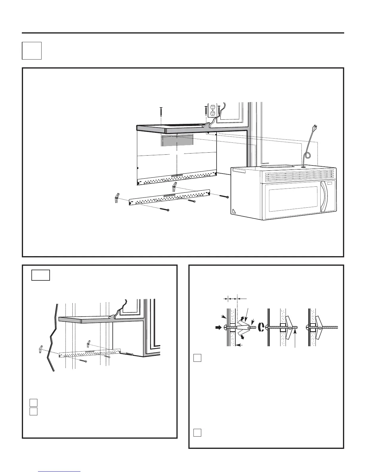
A1. Montaje de la placa de instalación en la pared.
A2. Preparación del gabinete superior.
A3. Ajuste del ventilador del microondas para la
extracción superior externa.
A4. Verificación del funcionamiento del
regulador de extracción.
A5. Instalación del horno microondas.
A6. Ajuste del adaptador de extracción.
A7. Acoplamiento del sistema de conductos.
NOTAS IMPORTANTES:
Asegúrese de que los tornillos
del-motor del ventilador y la placa
del ventilador queden firmemente
apretados al volver a instalarlos.
Esto ayudará a prevenir el exceso
de vibraciones.
Asegúrese de que el cableado del
motor quede debidamente orientado
y asegurado, y que los cables no
queden atrapados.
Fije la placa en la pared con los tornillos de fiador. Al menos un
tornillo para madera debe ser utilizado para fijar la placa a una
viga de la pared.
Quite las tuercas de mariposa de los tornillos.
Inserte los tornillos en la placa de instalación, a través de los
agujeros taladrados en las partes de la pared que no son viga
(los paneles) y vuelva a insertar las tuercas de mariposa hasta
3/4" (19 mm) de cada tornillo.
Coloque la placa de instalación contra la pared e inserte las
tuercas de mariposa en los agujeros de la pared, a fin de
instalar la placa.
NOTA: antes de apretar los tornillos de fiador y el tornillo para
madera, asegúrese de que las lengüetas de la placa de
instalación toquen la parte inferior del gabinete cuando sean
empujadas a ras contra la pared, y que la placa quede
debidamente centrada bajo el gabinete.
PRECAUCIÓN: tenga cuidado de evitar que sus dedos queden
atrapados entre la parte trasera de la placa de instalación y la
pared.
Apriete todos los tornillos. Tire de la placa alejándola de la
pared, a fin de que resulte más fácil apretar los tornillos.
SP-12
3
/
8
"
TO
EDGE






































NO
TE: IT IS
VERY IMP
O
RTANT
TO
READ AND FO
LLO
W THE
DI
RECTIO
NS
IN THE INST
AL
LATIO
N INST
RUCTIO
NS
BEFO
RE
PRO
CEEDING
WITH T
HIS
REAR W
ALL TEMP
LAT
E.
T
his
Rear
Wall
T
e
mplate
s
er
v
es
to
po
s
iti
o
n th
e
b
otto
m
mo
un
ting
p
lat
e and
to l
oc
a
te
t
he ho
r
iz
o
n
tal
e
xha
us
t
ou
tle
t.
1. Us
e a lev
el
to
c
he
c
k
tha
t th
e t
e
mpla
te
is
p
os
it
ion
ed
a
c
cur
ately
.
2. L
o
c
ate
and
ma
r
k
at le
as
t o
ne
s
tu
d on
th
e
left or
r
igh
t s
id
e
of t
he
c
en
te
r
lin
e.


It is
im
p
or
t
an
t to u
s
e a
t le
a
s
t one
w
o
o
d
s
c
r
e
w mou
nted
fi
r
mly
in
a
s
tud
to s
u
pp
o
rt th
e
we
igh
t
of th
e m
ic
r
owav
e
. Mar
k
two ad
diti
on
a
l, e
v
e
n
l
y
s
p
ac
ed
lo
c
a
tions
for
the
s
u
pp
li
ed
tog
gl
e b
o
lts
.
3. Dr
ill h
ole
s
i
n th
e
mar
k
e
d
l
o
catio
n
s
. Wher
e th
er
e
i
s
a
s
tud,
dr
il
l a
3/16"
ho
le for
woo
d s
c
r
e
ws
.
F
or
ho
le
s
th
at do
n
ot
lin
e u
p
with
a
s
tu
d
, dr
il
l
5/8"
ho
le
s
for
to
gg
le b
olts
.


DO
NO
T
IN
S
TA
LL T
HE
MO
UNT
IN
G
P
LA
T
E
A
T
T
HIS
T
IME
.
4
. R
e
mov
e th
e temp
late
fr
o
m th
e
r
ea
r
w
a
ll
.
5. Rev
ie
w the In
s
ta
llatio
n
In
s
tr
u
c
ti
on
bo
o
k
for
y
o
u
r
i
ns
ta
lla
tion
s
itu
atio
n
.
Locate and m
ark holes to align wit
h holes in th
e
mounting pl
ate.
IMPO
RTANT:
LO
CATE AT LE
AST O
NE STUD O
N EI
THER SIDE O
F
TH
E CENTERLINE.
MARK THE LO
CATI
O
N FO
R 2 ADDI
TIO
NAL, EVENLY
SPACE
D T
O
G
G
LE BO
LTS I
N THE MO
UNT
ING
PLATE
AREA.
Locate and mar
k holes to align w
ith holes in the
mounting plat
e.
IMPORTANT
:
LO
CATE
AT
LEAS
T O
NE S
TUD O
N EITHER SIDE O
F
THE CENT
ERLINE.
MARK THE LO
CAT
IO
N FO
R 2 ADDITI
O
NAL, EVENLY
SPA
CED TO
G
G
LE BO
LTS IN
T
HE MO
UNTIN
G
PLAT
E
AREA.
Trim t
he rear w
all
t
emp
late along
t
he d
ott
ed line.
Trim t
he rear w
al
l t
e
mp
late along
the d
ott
ed line.
















12"
4"
Da
rle
v
ue
lt
a
a
la
hoja
pa
r
a
c
ons
ult
a
r
la
v
e
r
s
ión
e
n
Es
pa
ñol
.

Table of Contents

Questions and Answers:

Question and Answer IconNeed help?

Do you have a question about the Frigidaire MWV150KB and is the answer not in the manual?

Frigidaire MWV150KB Specifications

General IconGeneral
Capacity1.5 cu. ft.
Power1000 Watts
Control TypeElectronic
Weight30.9 lbs
ColorBlack
Pre-Programmed SettingsYes
Child LockYes
Warranty1 Year Limited
TypeMicrowave Oven
Cooking ModesDefrost, Reheat

Related product manuals