3
/
8" T
O E
D
GE
NO
TE
: IT IS VE
RY IM
POR
T
AN
T
TO
RE
AD
A
ND
FOLL
OW
TH
E
DIR
EC
TIONS
IN T
HE IN
STA
L
LATIO
N
INS
TR
U
CTIO
NS
BEFO
RE
PR
OC
EED
ING
WITH
TH
I
S
RE
AR
W
ALL
TEMP
LA
TE
.
T
h
is
Re
ar
W
all
T
e
m
pl
a
t
e
s
erv
es
t
o
p
osit
i
on
t
h
e
bot
t
om
m
ount
ing
pla
t
e
a
nd
t
o
lo
c
a
t
e
t
he
h
or
i
z
o
nt
al
exhaust
ou
t
let
.
1.
Us
e
a
le
vel
t
o
check
t
hat
t
h
e
t
e
m
pla
t
e
is
posi
t
ione
d
accurat
ely.
2.
Loc
at
e
and
m
ark
a
t
lea
s
t
one
st
ud
on
t
he
l
ef
t
or
right
side
o
f
t
h
e
c
e
nt
er
l
ine.
I
t
is
im
port
ant
t
o
u
se
at
leas
t
on
e
woo
d
scr
e
w
m
oun
t
e
d
f
irmly
in
a
st
ud
t
o
s
up
port
t
he
wei
ght
of
t
h
e
m
i
crow
ave.
M
a
r
k
t
wo
a
ddit
ion
al
,
e
v
enly
spa
ced
loca
t
i
on
s
f
or
t
h
e
s
uppl
ied
t
og
g
le
bolt
s.
3.
Dr
i
ll
h
oles
in
t
h
e
m
ark
ed
l
oca
t
ion
s.
Wh
ere
t
h
er
e
i
s
a st
ud,
dri
ll
a
3
/
1
6"
ho
le
f
o
r
wood
screws.
F
o
r
h
ol
es
t
hat
do
n
ot
li
ne
up
wit
h
a
st
u
d,
d
r
il
l
5
/
8
"
hole
s
f
or
t
oggle
b
olt
s
.
DO
NO
T
I
N
S
T
ALL
T
HE
M
O
UNT
I
NG
P
LAT
E
AT
T
HI
S
T
I
M
E.
4.
Rem
o
v
e
t
he
t
em
plat
e
f
rom
t
he
rear
wall.
5.
R
eview
t
h
e
I
nst
alla
t
io
n
I
n
s
truc
t
ion
boo
k
f
or
y
our
inst
allat
io
n
sit
u
a
t
io
n.
Lo
cate
and
mar
k hol
es to
a
lig
n w
ith ho
l
es
in the
mo
u
nti
ng p
late
.
IMP
O
RTA
NT:
LOCATE
AT LE
A
ST ON
E
STU
D
O
N
EITH
ER
S
ID
E
O
F
TH
E
C
E
NTER
LIN
E
.
M
A
R
K TH
E L
OC
AT
ION FOR
2 AD
D
IT
I
O
NAL
,
EVEN
LY
SP
ACE
D TOGG
LE BO
LTS IN
THE
MOU
NTIN
G
PLA
TE
AREA.
Lo
cate
and
mar
k hol
es to
a
lig
n w
ith h
o
les
in the
mo
unti
ng
p
late
.
IMPORTA
NT:
LO
CATE
AT LE
AST ON
E
STU
D O
N EIT
H
ER
SIDE
O
F
TH
E CE
N
TER
LIN
E.
MA
RK TH
E
L
OCAT
IO
N FOR
2 AD
DIT
I
O
NAL
, EVEN
LY
SP
AC
E
D
TOGG
LE
BO
LTS
IN
THE
M
OU
NTI
N
G PLA
TE
AR
EA.
Trim
the
r
ea
r wa
ll te
mpla
te a
l
o
n
g the d
otted
line
.
Tri
m
the
r
ea
r
wall
te
mpla
te
a
l
o
ng
the
d
otted
lin
e
.
1
2
"
4
"
Dar
le
vu
elta
a
la
ho
ja
pa
r
a
co
n
sul
tar
la
ve
r
sión
en
E
spañ
ol.
Asegúrese de que los tornillos del
motor del ventilador y la placa del
ventilador queden firmemente
apretados al volver a instalarlos. Esto
ayudará a prevenir el exceso de
vibraciones.
Asegúrese de que el cableado del
motor quede debidamente orientado y
asegurado, y que los cables no queden
atrapados.
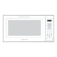
EXTRACCIÓN TRASERA EXTERNA (Conducto Horizontal)
DESCRIPCIÓN GENERAL DE LA INSTALACIÓN
B1. Preparación de la pared trasera
B2. Desinstalación del placa del ventilador
B3. Montaje de la placa de instalación en la pared
B4. Preparación del gabinete superior
B5. Ajuste del ventilador
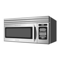
B6. Instalación del horno microondas
NOTAS IMPORTANTES:
Lea las instrucciones de la sección PLANTILLA PARA LA PARED
TRASERA.
Adhiera con cinta la plantilla a la pared trasera, alineándola
con los agujeros previamente taladrados pares coincidir con
los agujeros A y B en la placa para la pared.
Realice el corte de la abertura, siguiendo las instrucciones de
la sección PLANTILLA PARA LA PARED TRASERA.
PREPARACIÓN DE LA PARED
TRASERA PARA LA SALIDA DE
EXTRACCIÓN TRASERA EXTERNA
Es necesario realizar un corte en la pared trasera para crear una
abertura para la salida de extracción externa.
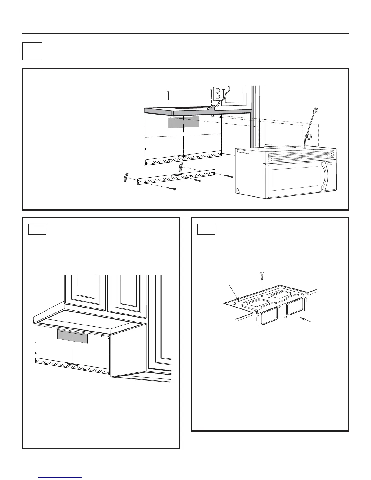
DESINSTALACIÓN DEL PLACA
DEL VENTILADOR
Quite y guarde el tornillo que sujeta la placa del ventilador al
microondas. Levante la placa del ventilador para retirarla.