8
Safety
Step 1:
Connecting the
Modbus wires
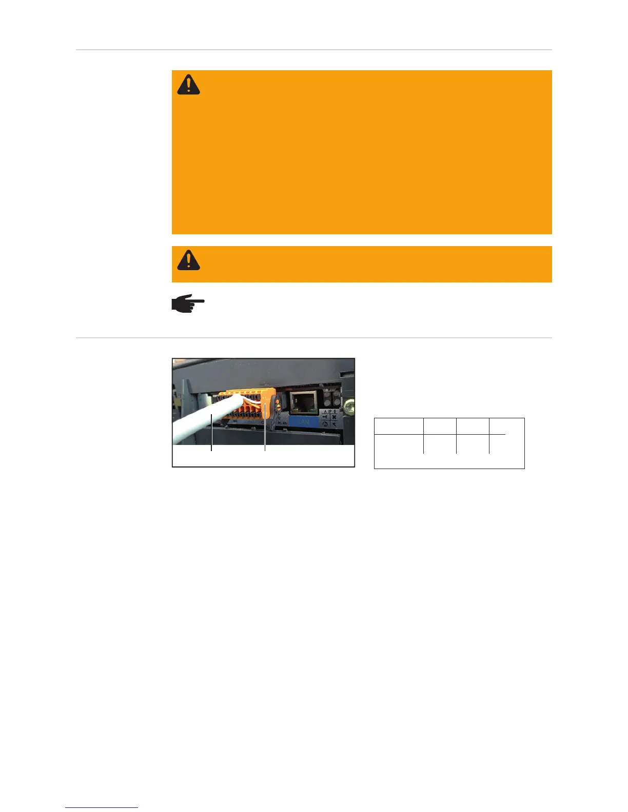
Connect the Modbus RTU (RS 485) cable
(1) to the modbus plug (2) of the Fronius
Datamanger 2.0.
Connect the orange wire to D+,
the white wire to D-
It is recommended that shielded CAT5 or CAT5e cables compliant with ISO 11801 and
EN50173 are used for Modbus RTU cabling.
Permitted cables:
S/STP, F/STP, S/FTP, F/FTP, SF/FTP, S/UTP, F/UTP, U/FTP, U/STP
The wires in the Ethernet cables are twisted in pairs. To prevent interference in the cables
only the following pairs of wires should be twisted together:
- data lines: D+ and D-
- when using the power supply: + and –
Information on connecting the cables:
- Make sure that the wires are assigned correctly
WARNING! An electric shock can be fatal. Danger from grid voltage and DC volt-
age from solar modules.
- The connection area should only be opened by a licensed electrician.
- The separate power stage set area should only be disconnected from the
connection area after first being disconnected from the grid power.
- The separate power stage set area should only be opened by Fronius-trained
service personnel.
Before making any connections, make sure that the AC and DC sides are discon-
nected from the inverter, e.g.:
- Switch off the AC automatic circuit breaker for the inverter
- Cover solar modules
Please observe the 5 safety rules.
WARNING! An electric shock can be fatal. Danger from residual voltage from ca-
pacitors.
You must wait until the capacitors have discharged.
NOTE! Follow general ESD precautions when handling plug-in cards.
(1) (2)
9
7
5
3
1
-
-
D-
8
6
4
2
0
+
+
D+
------I------ --IO-- RS485
IMPORTANT! Do not use ISO/IEC-11801 U/UTP cables!
 Loading...