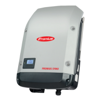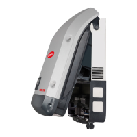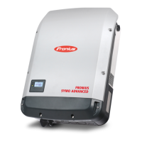


Do you have a question about the Fronius SYMO Series and is the answer not in the manual?
Explains warning symbols, general safety, and device handling.
Details operational environment and required personnel qualifications.
Covers noise emissions and electromagnetic compatibility.
Explains safety symbols and proper device disposal.
Provides procedures for data backup and copyright notice.
Overview of inverter components and valid software version.
Specifies authorized and unauthorized uses of the inverter.
Details compliance with radio standards.
Explains insulation monitoring and arc detection capabilities.
Highlights the importance of device warning labels.
Information on the use and specifications of string fuses.
Explains safety symbols and warning texts.
Provides criteria for selecting appropriate string fuses.
Explains the Fronius Solar Net system and data interface.
Details the physical data communication interface ports.
Details components, function, and switching variants of the interface.
Explains LED indicators and interface variants.
Demonstrates data logging with Datamanager and Sensor Box.
Explains IP address configuration and access points.
Explains status indication of various LEDs.
Details the LAN connection and digital input/output ports.
Covers Modbus, power, and antenna connections.
Explains master/slave switch and termination settings.
Availability during night or low DC voltage.
Warns about incorrect cable connections and installation.
Describes the App for initial setup.
Steps for first-time start and network setup.
Steps for installation using the Solar.start app.
Steps for installation via web browser connection.
Guides through setting up system monitoring.
Explains Solar Web and Technician wizards.
Explains the display and status LEDs.
Details the function and operation of the device's keys.
Describes display area and modes like NOW and Setup.
Explains symbols used for menu navigation and status.
How to activate and manage display illumination.
Steps to access and navigate through menus.
Lists and explains data displayed in the NOW menu.
Lists and explains data recorded in the LOG menu.
Shows max voltage and total operating time.
Covers initial configuration and software updates.
Instructions for accessing and scrolling through setup options.
Adjusting general menu item parameters.
Demonstrates setting the feed-in tariff.
Step-by-step guide to setting the feed-in tariff.
Activating/deactivating standby and restoring operation.
Guides on activating/deactivating the WLAN Access Point.
Configuration for data communication, inverter number, and protocol.
Performing firmware updates and managing USB logging.
Step-by-step guide for updating firmware via USB.
Explains relay function and modes.
How to set the logging interval for USB data.
Details GAF mode, active output, and application examples.
Information on using Energy Manager with the relay.
Guides for setting time, date, and display formats.
Information on setting switch-on/off points for Energy Manager.
Setting display language and automatic daylight saving.
Controls Datacom and display operation at night.
How to adjust display contrast and illumination.
Settings for meter calibration, currency, and feed-in tariff.
Procedure for testing the inverter's fan.
Steps to perform a self-test for arc detection.
Lists various measured DC and AC values.
Displays inverter status codes and grid errors.
Shows device type, family, and serial number.
Configuration for country setup and MPP tracking.
Settings for grid monitoring and voltage limits.
Settings for grid frequency limits and reactive power.
Details power reduction and version information.
Steps to activate or deactivate the key lock function using a code.
How to use the USB drive for logging data.
Recommendations for compatible USB thumb drives.
Indicates USB symbol and drive recognition.
Steps for updating software and safely removing the USB stick.
Steps to access the Basic menu using an access code.
Lists key parameters available in the Basic menu.
Configuration for DC modes, USB logbook, and signal input.
Settings for SMS/Relay, Insulation, and total reset.
How system self-diagnosis displays issues via status codes.
Troubleshooting steps for a blank display.
Guidance on contacting support and cleaning.
Electrical input and output specifications for the models.
Overall efficiency and frequency specifications.
Details efficiency, cooling, and physical dimensions.
Lists integrated protection mechanisms.
Electrical specs and grid voltage/current for 480V models.
Efficiency, dimensions, and protection features.
Electrical input and output parameters for the model.
Grid voltage, frequency, and general technical details.
Cooling method, protection class, and physical dimensions.
Ambient limits and integrated protection features.
Electrical specs and grid voltage/current for 480V models.
Efficiency, dimensions, and protection features.
Electrical specs and grid voltage/current for 480V models.
Efficiency, dimensions, and protection features.
Electrical specs and grid voltage/current for the model.
Efficiency, dimensions, and protection features.
Efficiency, dimensions, and integrated protection features.
Clarifies the meaning of footnotes used in technical data.
Details the circuit for preventing stand-alone operation.
Describes procedures for grid failure events.
Explains the Residual Current Monitoring Unit feature.
Information on warranty registration and conditions.
Instructions for environmentally sound disposal of the equipment.
| MPPT Number | 2 |
|---|---|
| Frequency Range | 50 / 60 Hz |
| Operating Temperature Range | -25°C to +60°C |
| Communication | WiFi, Ethernet, RS485 |
| AC Nominal Voltage | 3 x 230 V / 400 V |
| Output Voltage | 3 x 230 V / 400 V |
| Warranty | 5 years |


