Display Power for the display comes from the AC grid voltage. The display can be avail-
able all day long depending on the setting in the Setup menu.
IMPORTANT! The inverter display is not a calibrated measuring instrument.
Slight deviation from the utility company meter is intrinsic to the system. A calib-
rated meter is required to make calculations for the utility company.
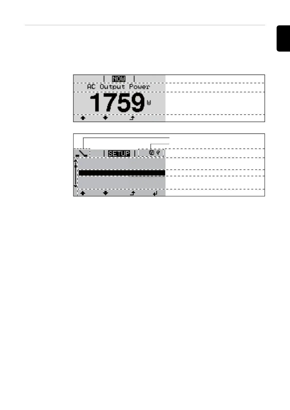
Function key functions
Menu item
Parameter declaration
Display of values, units and status codes
Display area, display mode
Function key functions
Next menu items
Currently selected menu item
Previous menu items
Menu item
Inv. no. | Save symbol | USB conn.(***)
(*)
1
Energy-Manager (**)
Standby
WiFi Access Point
DATCOM
USB
Relay
Display area, setup mode
(*) Scroll bars
(**) The Energy Manager symbol
is displayed, if the Energy Manager function has been activated
(***) WR no. = Inverter
DATCOM number,
Store icon – appears briefly when set values are stored,
USB connection – appears if a USB flash drive has been inserted
25
EN-US