9
EN-US
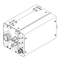
- The ground connections of the shielding can be done in the following ways:
- Common ground connection:
Connect the shielding of the incoming and outgoing cables and at one end of the
data cabling ground all the shielding together.
- Separate ground connection:
Ground each shield on only one side of the cable
- The Data-GND-lines (–) off all devices in the modbus RTU system have to be connect-
ed.
The following structured cabling standards must generally be observed:
- EN50173-1 for Europe
- ISO/IEC 11801:2002 internationally
- TIA/EIA 568 for North America
The rules for use of copper cables are valid.
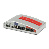
Step 2:
Setting the line
termination resis-
tor
To minimize interference due to reflections from the end of the RS485 cable, it is required
to place a line termination (resistor) near each of the 2 ends of the bus.
Each Fronius Datamanager 2.0 possesses such a line termination resistor, which can be
added or removed by means of a small switch (1) on the Datamanager 2.0.
Only set the switch (1) on the last Fronius
Datamanager 2.0 of the RS 485 bus to
ON (2).
Step 3: Changing
the inverter num-
ber
If more than one Fronius inverter is connected to the same Modbus network, it is important
that all inverters have different Fronius DATCOM inverter numbers. It is irrelevant whether
there is only one or several Fronius Datamanagers 2.0 present.
The Fronius DATCOM inverter number equals the Modbus ID, which is necessary to
adress the respective device.
Note that inverter number 0 represents Modbus ID 100, because Modbus ID 0 is reserved
for broadcast messages.
IMPORTANT! The shielding and any unused wire pairs must not be connected to a GND
pin of the Fronius Datamanager 2.0.
GND
(1) (2)
NOTE! Leave the switches of all
other devices to OFF!
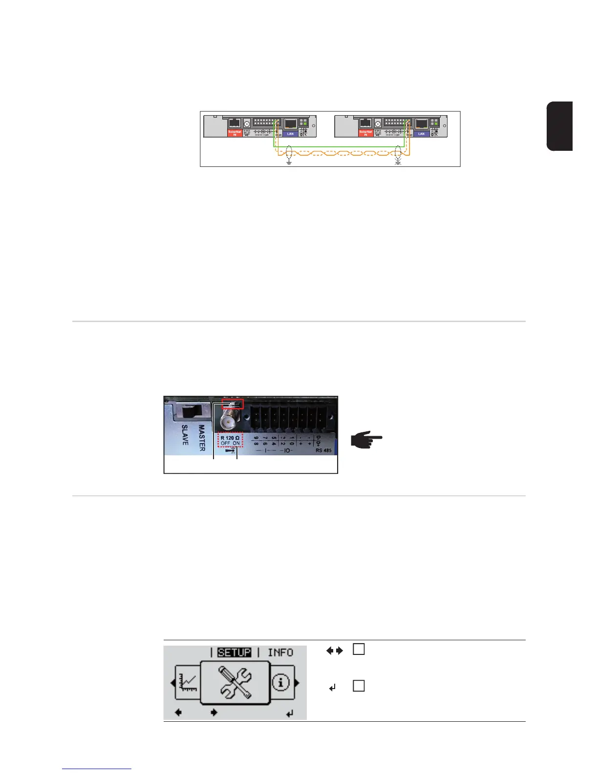
Example:
How to set the inverter number on a Fronius Galvo or Symo inverter.
On the menu level, use the 'Left' or
'Right' keys to select the 'SETUP'
menu item
Press the 'Enter' key
GRAPH
1
2
 Loading...