30
Remove plastic film
Ensure that the cooling unit is discon-
nected from all system components
and remains so for the duration of all
work
Unscrew the three screws from the
right side panel (as seen from the
front) of the cooling unit and remove
the side panel
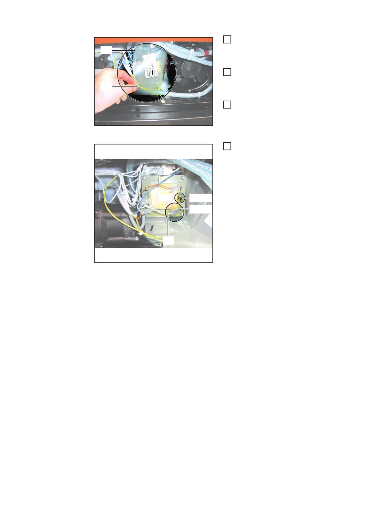
Loosen and remove the plastic film
(1) on the clip (2)
Change the auto-transformer connections (example
shows FK 4000 R US)
Change the auto-transformer con-
nections according to the circuit dia-
gram: connect the white cable (3) to
the required mains voltage (the im-
age to the left shows the reconnec-
tion of the auto-transformer using the
FK 4000 R US as an example. The
reconnection is carried out in the
same way for other units; only the
possible voltages differ.
- In the circuit diagram for the unit,
the factory configuration is
shown by a solid line and the oth-
er options by a dashed line.
The circuit diagram can be found
on the inside of the side panel.
(1)
(2)
1
2
3
(3)
(440 V)
(460 V)
4