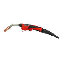
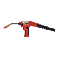
The PullMig is a wire feed unit designed for manual welding applications using soft welding wires and long hose packs. It features two toothed precision rolls that ensure large-surface power transmission, leading to outstanding wire feed even with very soft aluminum and CuSi wires, and over long hose packs. A distinguishing feature of the PullMig is its availability in many different versions, including several variations of torch connections with both external and internal coolant connections. The variety of pipe bend designs ensures excellent weld accessibility.
Proper Use:
The MIG/MAG manual welding torch is intended solely for MIG/MAG welding in manual applications. Any use beyond this purpose is considered improper, and the manufacturer will not be held liable for damages arising from such usage. Proper use includes carefully reading and following all instructions in the operating manual and performing all stipulated inspection and maintenance work.
- Danger from incorrect operation and improper work: All work and functions described in this document must be carried out by technically trained and qualified personnel. Users must read and understand this document in full, as well as all safety rules and user documentation for the device and all system components. Failure to do so can result in serious personal injury and property damage.
- Danger from electrical current: Before starting work, all involved devices and components must be switched off and disconnected from the grid. These devices and components must be secured to prevent accidental re-activation. After opening the device, a suitable measuring instrument should be used to check that electrically charged components (such as capacitors) have been discharged. This can result in serious personal injury and property damage.
- Danger from electric current due to defective system components and incorrect operation: All cables, leads, and hosepacks must always be securely connected, undamaged, and correctly insulated. Only adequately dimensioned cables, leads, and hosepacks should be used. This can result in serious personal injury and property damage.
- Danger due to emerging wire electrode: The welding torch should be held so that its tip points away from the face and body. Suitable protective goggles must be worn. The welding torch should not be pointed at people, and the wire electrode must not touch any electrically conductive objects. This can result in serious personal injury.
- Danger due to hot system components and/or equipment: Before starting work, all hot system components and/or equipment (e.g., coolant, water-cooled system components, wirefeeder drive motor) should be allowed to cool to +25°C/+77°F. If cooling down is not possible, suitable protective equipment (e.g., heat-resistant gloves, safety goggles) must be worn. This can result in serious burns or scalding.
- Danger from operation without coolant: Water-cooled welding torches must never be operated without coolant. During welding, ensure that the coolant is circulating correctly; for Fronius cooling units, a regular return flow of coolant should be visible in the coolant container. The manufacturer will not be liable for any damages due to non-observance of these points, and all warranty claims will be void. This can result in damage to property.
- Danger due to exposed mechanically moving parts: The device should only be operated when all covers are closed and/or completely mounted. This can result in personal injury and property damage.
System Requirements:
- Power source: TS 4000/5000 or TPS 2700/4000/5000.
- Software: Power source software version 3.10.22 or higher; Wire feed software version 1.70.16 or higher.
- Options: Installation set "PMR4000 PullMig TS/TPS 2700-5000 (4,100,217)" and software "FS Drive (4,061,113)".
Installation and Commissioning:
- Mounting the torch neck: When mounting the torch neck, especially on water-cooled welding torches, ensure the swivel nut is fixed firmly to prevent coolant leakage or damage from overheating on gas-cooled torches.
- Assemble wire guidance insert: When cutting the inner liner to length, ensure no burr (sharp edges) protrudes into the inner liner at the cut location. Hold side-cutting pliers at a slight angle to pull the burr outwards, then grind it off.
- Available wire guidance inserts: Ø 4 mm (.16 in.) (40,0002,0014; 40,0002,0015) and Ø 4.7 mm (.19 in.) (40,0002,0004; 40,0002,0017).
- Assemble Inner Liner (Fronius connection without wire-guidance nozzle): Bring the inner liner as close as possible to the wirefeed rollers, but without touching them. Before threading in the welding wire, round off the ends of the wire.
- Assemble Inner Liner (Fronius connection with wire-guidance nozzle): Only use wire guidance nozzles corresponding to the wire diameter. Available nozzles: 0.8 mm (.030 in.), 1.0 mm (.040 in.), 1.2 mm (.045 in.), 1.6 mm (1/16 in.). Before threading in the welding wire, round off the ends of the wire.
- Assemble Inner Liner (Euro connection without wire-guidance nozzle): Bring the inner liner/infeed nozzle as close as possible to the wirefeed rollers, but without touching them. Before threading in the welding wire, round off the ends of the wire. An optional infeed nozzle (42,0001,5421) is available.
Maintenance Features:
- Replace Feed Rolls:
- Unscrew pressure lever (1).
- Unscrew axle (2) using a slotted screwdriver.
- Remove complete unit (3).
- Fix drive roll (4) using the provided driving gear key (5).
- Unscrew hexagon nut (6) using an open-ended spanner (size 10 mm / .394 in.).
- Remove drive roll (4).
- Set Electrode Pressure: Three settings are available: hard (e.g., CrNi), medium (e.g., AlMg/CuSi), and soft (e.g., AlSi).
- Replace Wire Inlet Nozzle:
- Unscrew hexagon nut (1) using an open-ended spanner (size 10 mm / .394 in.).
- Unscrew and remove wire inlet nozzle using an Allen key (2) (key width 2.5 mm / .099 in.).
Usage Features:
- Up/Down Function: Allows setting welding output using the Up/Down switch. The switch can be changed to either side if required.
- JobMaster Function: Select and set desired parameters using the JobMaster function. Refer to the MIG/MAG Torch Operating Instructions, chapter "JobMaster," for more detailed information.
Important Technical Specifications:
PullMig hosepack gas-cooled:
- Current (I Amp.) 10 min/40° C M21 (EN 439) - d.c.: 40% ED* 280 A, 60% ED* 220 A, 100% ED* 170 A.
- Current (I Amp.) 10 min/40° C C1 (EN 439) - d.c.: 40% ED* 330 A, 60% ED* 270 A, 100% ED* 210 A.
- Length (m/ft.): 6/8/10 (19.6/26.2/32.8).
- Voltage (U V DC): 42 V.
- Idle Current (I A): 0.8 A.
- Wire Speed (m/min / ipm): 0.5 - 18 (19.69 - 787.40).
- Wire Diameter (Ø mm / in.): 0.8 - 1.6 (.032 - .047).
PullMig hosepack water-cooled:
- Current (I Amp.) 10 min/40° C M21 (EN 439) - d.c.: 100% ED* 400 A.
- Current (I Amp.) 10 min/40° C C1 (EN 439) - d.c.: 100% ED* 500 A.
- Length (m/ft.): 6/8/10 (19.6/26.2/32.8).
- Min. Power (Pmin W): 1450 / 1800 / 2000 W.
- Min. Flow (Qmin l/min / gal./min): 1 (.26).
- Min. Pressure (Pmin bar / psi): 3 (43.5) and 5.5 (79.7).
- Voltage (U V DC): 42 V.
- Idle Current (I A): 0.8 A.
- Wire Speed (m/min / ipm): 0.5 - 18 (19.69 - 787.40).
- Wire Diameter (Ø mm / in.): 0.8 - 1.6 (.032 - .047).
- d.c. = duty cycle
- Minimum cooling power in accordance with standard IEC 60974-2
PullMig torch neck gas-cooled (various models):
- AL216: M21: 35% 180A, 60% 140A, 100% 100A. C1: 35% 210A, 60% 160A, 100% 120A. Wire Ø: 0.6-1.0mm.
- AL236: M21: 40% 200A, 60% 160A, 100% 120A. C1: 40% 230A, 60% 190A, 100% 150A. Wire Ø: 0.6-1.0mm.
- AL306: M21: 40% 260A, 60% 210A, 100% 160A. C1: 40% 300A, 60% 240A, 100% 190A. Wire Ø: 0.8-1.2mm.
- AL406: M21: 40% 350A, 60% 280A, 100% 220A. C1: 40% 400A, 60% 320A, 100% 250A. Wire Ø: 1.0-1.6mm.
- AL2300: M21: 40% 200A, 60% 160A, 100% 120A. C1: 40% 230A, 60% 190A, 100% 150A. Wire Ø: 0.6-1.0mm.
- AL2400: M21: 40% 200A, 60% 160A, 100% 120A. C1: 40% 240A, 60% 200A, 100% 160A. Wire Ø: 0.6-1.0mm.
- AL3000: M21: 40% 250A, 60% 200A, 100% 150A. C1: 40% 400A, 60% 320A, 100% 250A. Wire Ø: 0.8-1.2mm.
- AL4000: M21: 40% 350A, 60% 280A, 100% 220A. C1: 40% 400A, 60% 320A, 100% 250A. Wire Ø: 1.0-1.6mm.
PullMig torch neck water-cooled (various models):
- AW252: M21: 100% 220A. C1: 100% 250A. Wire Ø: 0.6-1.2mm.
- AW332: M21: 60% 200A, 100% 150A. C1: 60% 250A, 100% 190A. Wire Ø: 0.8-1.2mm.
- AW335: M21: 60% 200A, 100% 150A. C1: 60% 250A, 100% 190A. Wire Ø: 0.8-1.2mm.
- AW352: M21: 100% 300A. C1: 100% 350A. Wire Ø: 1.0-1.6mm.
- AW502: M21: 100% 400A. C1: 100% 500A. Wire Ø: 1.0-1.6mm.
- AW652: M21: 100% 500A. C1: 100% 600A. Wire Ø: 1.0-2.4mm.
- AW2500: M21: 100% 220A. C1: 100% 250A. Wire Ø: 0.6-1.2mm.
- AW4000: M21: 100% 350A. C1: 100% 400A. Wire Ø: 0.8-1.2mm.
- AW5000: M21: 100% 400A. C1: 100% 500A. Wire Ø: 1.0-1.6mm.
- AW7000: M21: 100% 550A. C1: 100% 700A. Wire Ø: 1.0-1.6mm.
PullMig - hosepack / torch neck:
- Voltage rating (V-Peak): 113 V for manually guided torches, 141 V for mechanically guided torches.
- The product complies with standard IEC 60974-7.
PushPull Equalisation:
- PushPull equalisation is adjusted in accordance with the Power Source Operating Instructions, chapter "PushPull Unit."