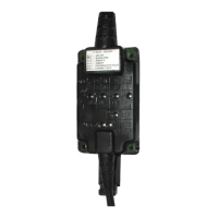
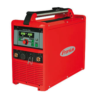
The Fronius RI IO PRO/i is an interface designed for integrating Fronius welding power sources with robotic control systems, facilitating automated welding processes. It features both analog and digital inputs and outputs, allowing for versatile operation in either standard mode or Open Collector (OC) mode, with mode selection managed via a jumper.
Function Description
The RI IO PRO/i acts as a crucial link between a robot control and a welding power source, enabling the robot to send commands and receive feedback for precise welding operations. It supports a wide range of digital input signals from the robot to the power source, including:
- Welding start: Initiates the welding process.
- Robot ready: Indicates the robot's operational status.
- Gas on: Controls the gas flow.
- Wire forward/backward: Manages wire feed direction.
- Torch blow out: Activates torch cleaning.
- Touch sensing: Enables touch-sensing functionality for seam tracking.
- Teach mode: Engages robot teaching mode.
- Welding simulation: Activates welding simulation.
- Error reset: Clears error states.
- Torchbody Xchange: Signals a torch body change.
- WireBrake on: Engages the wire brake.
The interface also handles analog input signals from the robot to the power source, such as:
- Wire feed speed command value: Sets the desired wire feed speed.
- Arclength correction: Adjusts the arc length.
- Pulse-/dynamic correction: Modifies pulse and dynamic characteristics.
- Wire retract correction: Controls wire retraction.
For feedback to the robot, the RI IO PRO/i provides digital output signals from the power source, including:
- Arc stable / Touch signal: Indicates arc stability or touch sensing activation.
- Power source ready: Signals the power source's readiness.
- Collisionbox active: Shows if the collision box is active.
- Process active: Indicates an active welding process.
- Main current signal: Provides the main current status.
- Touch signal: Confirms touch sensing.
- Current flow: Indicates current flow.
- Torchbody gripped: Confirms the torch body is gripped.
Analog output signals from the power source to the robot are also available for process monitoring and documentation:
- Welding voltage: Outputs the actual welding voltage.
- Welding current: Outputs the actual welding current.
- Wire feed speed: Outputs the actual wire feed speed.
- Motor current M1: Outputs the motor current.
- Actual real value for seam tracking: Provides real-time data for seam tracking.
The interface supports different "Working modes" (Internal parameter selection, Special 2-step mode characteristics, Job mode) and "Welding characteristic / Job number" selection via bit coding, allowing the robot to recall stored welding parameters. In "Retrofit Mode," specific program numbers (1-255) can be assigned to characteristic IDs for compatibility with older TPS series power sources.
Important Technical Specifications
- Operating Modes: Standard mode, Open Collector (OC) mode (selectable via jumper).
- Digital Input Signal Levels:
- Low (0): 0 - 2.5 V
- High (1): 18 - 30 V
- Reference Potential: GND (X2/2, X3/3, X3/10, X6/4)
- In OC mode, all signals are inverted (inverted logic).
- Analog Input Signal Levels: Active at voltages of 0 - 10 V. If individual analog inputs are unassigned, the values set at the power source are used.
- Digital Output Power Supply: Requires a voltage of no more than 36 V at connector X6/1. Can be supplied with 24 V from the interface or a customer-specific voltage (0 - 36 V). The 24 V secondary output voltage is galvanically isolated from the SpeedNet connection, with a protective circuit limiting the voltage level to 100 V.
- Ambient Temperature Range:
- Operation: 0 °C to +40 °C (32 °F to 104 °F)
- Transport and Storage: -25 °C to +55 °C (-13 °F to 131 °F)
- Relative Humidity: Up to 50% at 40 °C (104 °F), up to 90% at 20 °C (68 °F).
- Ambient Air: Free of dust, acids, corrosive gases or substances.
- Altitude: Up to 2000 m (6500 ft).
- Connectors: X1, X2, X3, X4, X5, X6, X7, X8 (for SpeedNet supply).
- Indicators (LEDs): +24 V, +15 V, -15 V, +3V3 (for power supply status), Arc stable / Touch signal, Robot ready, Error reset, Welding start, Power source ready.
Usage Features
- Easy Integration: Supplied with cable harnesses for connecting to both the power source and the robot control. The interface-side cable harness is pre-configured with Molex plugs.
- Flexible Operation: Supports both standard and Open Collector modes, adaptable to different robot control requirements.
- Parameter Management: Allows the robot to select stored welding characteristics or job numbers via bit coding, streamlining process changes.
- Retrofit Compatibility: Enables the use of 8-bit program signals from older TPS series power sources by assigning program numbers to characteristic IDs via the power source's web interface.
- Galvanic Isolation: Analog differential amplifier inputs ensure electrical isolation between the interface and the robot control's analog outputs, enhancing system reliability.
- Diagnostic Indicators: LEDs provide visual feedback on power supply status and key operational signals (Arc stable, Robot ready, Welding start, Power source ready), aiding in troubleshooting.
Maintenance Features
- Installation: Designed for installation on a DIN rail in a switch cabinet for machines or robots.
- Safety Precautions: Emphasizes the importance of disconnecting power, securing devices against re-engagement, and discharging electrical components before any work. It also warns against transmitting safety-critical signals via the interface and highlights the need for adequate ground conductor connection.
- Signal Status on Disconnection: If the connection between the power source and the interface is interrupted, all digital and analog output signals on the interface are set to "0," providing a predictable fail-safe state.
- Documentation: References a separate document, "TPS/i interface signal descriptions," for detailed information on specific signals, which is essential for maintenance and configuration.
- Environmental Protection: Requires storage and operation within specified environmental conditions to prevent device damage.