Do you have a question about the Fronius MHP 280i G CMT and is the answer not in the manual?
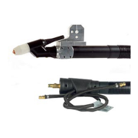
Specifies the intended manual applications for the MIG/MAG welding torch.
Details required original equipment kits for hosepack usage with various materials.
Describes the functions of the Up/Down torch, including power control and error display.
Instructions for deactivating individual or both torch triggers.
Procedure for reactivating both torch triggers.
Details safety symbols and rating plate warnings against incorrect operation and potential injury.
Highlights critical operational warnings regarding incorrect use and electrical hazards.
Lists cautionary warnings related to thermal hazards, coolant, and moving parts.
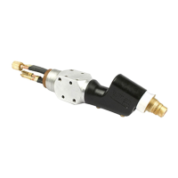
Step-by-step guide for fitting wearing parts to the torch body, including nozzle attachment.
Important note on using a steel inner liner for gas-cooled torches at maximum power.
Identifies issues with push application clamping nipples and suggests using brass nipples.
Addresses issues with push-pull clamping nipples and recommends silver nipples.
Guidance on selecting the correct outlet nozzle based on wire diameter, e.g., red for 0.8-1.2mm.
Note on ensuring the hosepack is straight for correct inner liner insertion.
Instructions for attaching the torch body, ensuring alignment and tightening the union nut.
Procedure for fitting the inner liner to the wire buffer, securing the sliding contact at the torch end.
Details on connecting torch to power source and cooling unit, emphasizing coolant hose connection.
Safety measures for handling the wire electrode, including preventing injury and arc ignition.
Guide on setting contact pressure by turning the adjustment screw clockwise or counter-clockwise.
Procedure for removing the torch body, including cooling instructions and nozzle orientation.
Steps for rotating the torch body, including cooling requirements and securing the union nut.
Highlights the importance of regular preventive maintenance for trouble-free operation and heavy soiling.
Details checks and replacements for wearing parts, gas nozzle, spatter guard, and coolant connections.
Instructions for cleaning the wirefeeding hose and replacing the inner liner when changing the spool.
Lists common faults and wear indicators for various torch components like nozzles and contact tips.
Note on ensuring the hosepack is straight for correct inner liner insertion into the drive unit.
Diagnoses and remedies for issues where there is no welding current despite power source indicators being lit.
Troubleshooting steps for when the torch trigger does not activate any function.
Identifies causes and solutions for the absence of shielding gas when other functions are operational.
Addresses poor weld properties due to incorrect parameters, grounding, and shielding gas issues.
Discusses factors like contaminated shielding gas and workpiece condition affecting weld quality.
Covers problems related to clamping nipples, gas nozzles, and shielding gas flow turbulence.
Explains how torch distance and tilt angle impact weld seam quality.
Troubleshooting wirefeeding issues caused by mismatched components or excessive brake force.
Addresses problems with contact tips, defective inner liners, and unsuitable wirefeeder rollers.
Covers issues with soiled rollers, incorrect inner liner fitting, and cut inner liners.
Discusses wire electrode wear due to contact pressure and issues with impurities or coating.
Addresses torch overheating due to loose union nuts, exceeding current limits, or inadequate coolant flow.
Examines torch overheating related to specifications, duty cycle, and coolant flow adequacy.
Identifies causes for short contact tip life, including roller problems, electrode quality, and tip dimensions.
Discusses contact tip overheating due to lack of thermal dissipation from a loose fit.
Troubleshooting torch trigger malfunctions due to faulty plug connections or dirt buildup.
Addresses weld seam porosity caused by spatter, gas hose problems, or faulty O-rings.
Covers porosity related to gas flow, electrode quality, and shielding gas escaping through liners.
Discusses the impact of excessive parting agent application on weld seam quality.
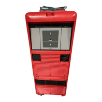
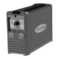
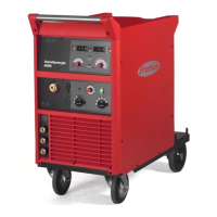
Provides general technical data, voltage measurements, trigger specifications, and product conformity.
Details technical specifications for the gas-cooled welding torch, including current and wire diameter.
Lists technical specifications for the water-cooled torch, covering current, wire diameter, and pressure.
| Input Voltage | 3 x 400 V |
|---|---|
| Rated Output Current | 280 A |
| Protection Class | IP23 |
| Welding Process | MIG/MAG |
| Input Frequency | 50/60 Hz |
| Output Current Range | 280 A |
| Duty Cycle | 280 A |