3
EN
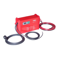
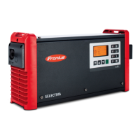
Fig. 1 Control panel and connections on the front
(4)
(1)
(3)
Controls and connections
Controls and
connections
(1) Mains cable/plug
(2) LocalNet connection socket (if remote control option in use)
- A standardised 10-pin connection socket is available for the LocalNet option. A
remote control or a relay board can be connected to the LocalNet socket.
(3) (+) lead
(4) (-) lead
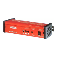
(5) Multifunction panel with integrated display and membrane keypad
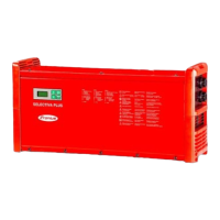
(6) Remote control RCS 01
(7) Power plug
(5)
(2)
(6)
(7)
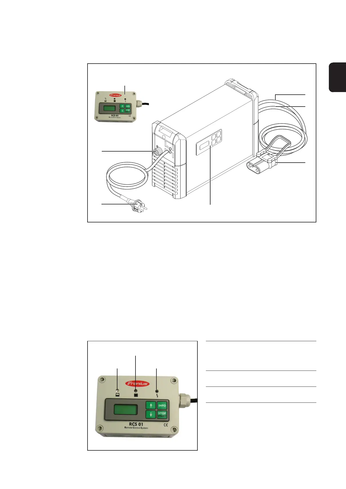
Yellow LED
lights up during operation
flashes after the set operating hours limit
has expired
Red LED
lights up if an error occurs
Green LED
does not function in this version
RCS 01 remote
control
Remote control RCS 01
Red LED
Green LED
Yellow LED
The power device remote control RCS 01 is operated in the same way as the power
device multifunction panel (see „Setup Menu“ section).