5
9b
14b
PV1
+
PV1
+
PV2
+
PV2
+
BAT
+
PV1
-
PV1
-
PV2
-
PV2
-
BAT
-
L1'
N'
N'
L1 N
max. length
Manufacturer manual
1
2
12 mm
max. 7 mm
max. 9 mm
CU-Wire min:
75°C / 167°F
Ø4-10 mm²
PV1
+
PV1
+
PV2
+
PV2
+
BAT
+
PV1
-
PV1
-
PV2
-
PV2
-
BAT
-
Manufacturer manual
RS 485
Inver
Parallel
R 120 Ω
Activated
01
Modbus 1
01
Modbus 0
Modbus 1
(min. CAT 5)
Modbus 0
(min. CAT 5)
4
8b
14a
18
23
19
3
9a
13
OFF
AC~
max. 63 A
1
OFF
1
10
6
15
20
12
8a
2
11
16
7
17
2221
2
BYD-XXXX
Secured
Password:
BYDB-Box
Serialnumber
Be Connect
BYD-XXXX
Secured
Password:
BYDB-Box
Serialnumber
1 2
open access point
Setup your PV system in a few minutes.
START INSTALLATION
LOGIN
Log in with your Fronius credentials (email adress
& password) in order to get the most out of the
PV System. Installing a new product does not
require a Login.
Imprint & ContactTerms & ConditionsData Privacy
Fronius Solar.start
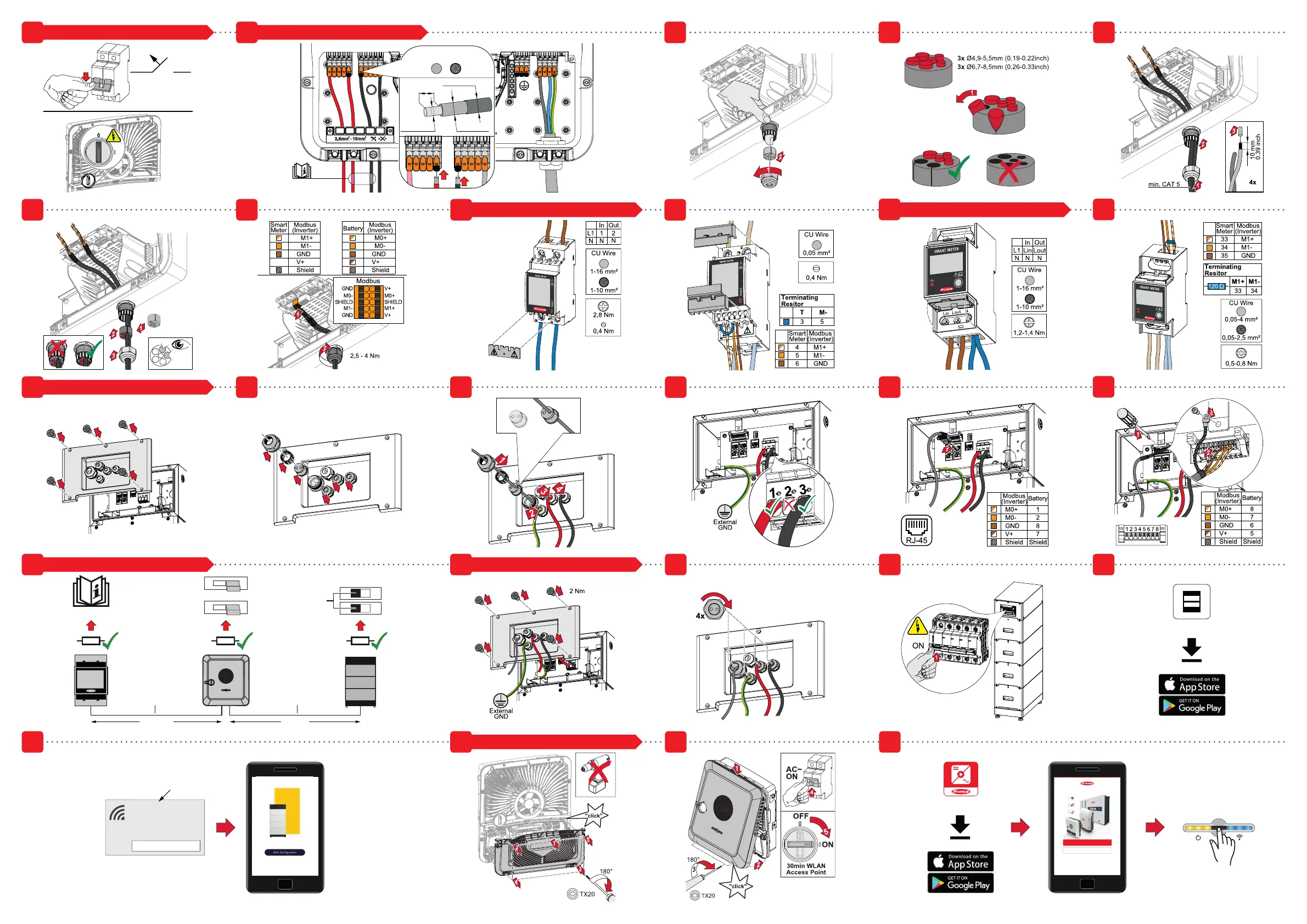
SWITCH OFF INVERTER (Step: 1) CONNECT BATTERY TO INVERTER (Steps: 2-7)
CONNECT SMART METER TS 100A-1 (Steps: 8-9) CONNECT SMART METER 63A-1 (Steps: 8-9)
CONNECT BATTERY (Steps: 10-17)
SETUP TERMINATING RESISTOR (Step: 15) BATTERY COMMISSIONING (Steps: 16-20)
INVERTER COMMISSIONING (Steps: 21-23)

 Loading...


