EasyManua.ls Logo

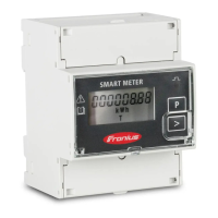
Fronius Smart Meter TS 65A-3 User Manual

Fronius Smart Meter TS 65A-3
40 pages
To Next Page IconTo Next Page
Page #1 background imageLoading...
Page #1 background image
Fronius prints on elemental chlorine free paper (ECF) sourced from certified sustainable forests (FSC).
/ Perfect Charging / Perfect Welding / Solar Energy
Fronius Smart Meter TS 100A-1
EN
Operating instructions
PV system monitoring
42,0426,0350,EN 007-22102020
www.youtube.com/FroniusSolar
LEARN MORE WITH
OUR HOW-TO VIDEOS

Other manuals for Fronius Smart Meter TS 65A-3

Question and Answer IconNeed help?

Do you have a question about the Fronius Smart Meter TS 65A-3 and is the answer not in the manual?

Fronius Smart Meter TS 65A-3 Specifications

General IconGeneral
Frequency Range50 Hz / 60 Hz
Communication InterfaceModbus RTU
MountingDIN rail
Power Consumption< 2 W
Protection ClassIP20
Measurement CategoryCAT III
Operating Temperature-25 °C to +55 °C
Nominal Voltage230 V / 400 V
Accuracy Active EnergyClass B according to EN50470-3
Accuracy Reactive EnergyClass 2
Storage Temperature+70 °C

Summary

Safety Rules

Safety Notice Symbols and Warnings

Understanding hazard symbols, DANGER, WARNING, CAUTION, and NOTE indicators.

General Safety Guidelines

General safety rules for operating personnel and the device.

Personnel, Environment, and Data Protection

Requirements for qualified personnel, environmental conditions, and data handling.

General Information

Fronius Smart Meter TS Overview

Description of the Fronius Smart Meter TS and its core functionality.

Scope of Supply and Mounting Positions

Contents of the delivery package and available installation locations.

Installation Procedure

Installation Checklist

A step-by-step checklist for proper installation.

Meter Mounting and Protective Circuit

Instructions for mounting the meter on a DIN rail and connecting protective circuits.

Cabling

Detailed instructions for connecting mains voltage cables.

Data Communication Cable Connection

Steps for connecting the data communication cable to the inverter.

Terminating Resistors Setup

Explanation and connection of terminating resistors for Modbus communication.

Connection Cover and System Symbols

Instructions for fitting covers and explanation of multi-meter system symbols.

System Integration and Start-up

SnapINverter Connection and Setup

Configuring the meter for SnapINverter systems as primary or secondary.

SnapINverter Secondary Meter Setup

Steps to configure the Smart Meter as a secondary meter with SnapINverter.

GEN24 Inverter Web Installation

Installing the meter with GEN24 inverter using a web browser.

GEN24 Meter Configuration

Configuring the meter as primary or secondary for GEN24 inverter systems.

Technical Specifications

Measuring Input Parameters

Details on voltage, current, frequency, and power factor of the input.

Data Output and Communication Standards

Information on RS485 communication, baud rate, and protocol.

EMC, Insulation, and Environmental Ratings

EMC compliance, insulation voltage, and operating condition specifications.

Housing and Terminal Specifications

Details on housing, mounting, and terminal wire sizes.

Related product manuals